
Power grid simulator topological structure and control method thereof

A technology of grid simulator and topology structure, which is applied in the direction of instruments, measuring electricity, photovoltaic power generation, etc., can solve problems such as static difference, output delay, and inapplicability of large-capacity systems, and achieve the effects of cost reduction and high response accuracy

Active Publication Date: 2021-06-01
JIANGSU GOLDWIND SCI & TECH CO LTD +1
View PDF7 Cites 3 Cited by
  • Summary
  • Abstract
  • Description
  • Claims
  • Application Information

AI Technical Summary

Problems solved by technology

[0003] The existing topological structure of the power grid simulator mostly adopts uncontrollable rectification at the front stage and three-phase PWM inverter structure at the rear stage, but it cannot realize four-quadrant operation, and it is only suitable for medium and low-voltage small-capacity systems, and is not suitable for large-capacity systems
At present, the control strategies of the grid simulator mainly include proportional integral control, repetitive control, sliding mode variable control, etc., but the proportional integral controller can only track the amplitude of the grid without difference, and there is a static difference value for the tracking of the given voltage. , time delay and oscillation; repetitive control has good steady-state output characteristics and robustness, but there is a problem of output delay of one fundamental cycle and poor dynamic performance; sliding mode variable structure is nonlinear control, open and close Control characteristics, resulting in chattering phenomenon, etc.

Method used


Image

  • Power grid simulator topological structure and control method thereof
  • Power grid simulator topological structure and control method thereof
  • Power grid simulator topological structure and control method thereof

Examples


Embodiment Construction

[0025] In order to make the purpose, technical solution and advantages of the present application clearer, the present application will be further described in detail below in conjunction with the accompanying drawings and embodiments. It should be understood that the specific embodiments described here are only used to explain the present application, and are not intended to limit the present application.

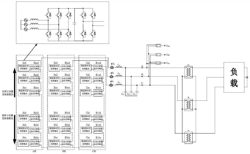
[0026] In one embodiment, combined with figure 1, provides a grid simulator topology, the topology includes: A, B, C three-phase, A, B, C three-phase LC filter, A, B, C three-phase transformer, and load; A, B The three phases A, B, and C respectively output fundamental waves, low-order harmonics, and high-order harmonics, and then connect the load through A, B, and C three-phase LC filters and A, B, and C three-phase transformers in turn.

[0027] The whole system is decomposed into two parts: the fundamental part and the harmonic part. The topology is composed of the fun...


PUM


Abstract

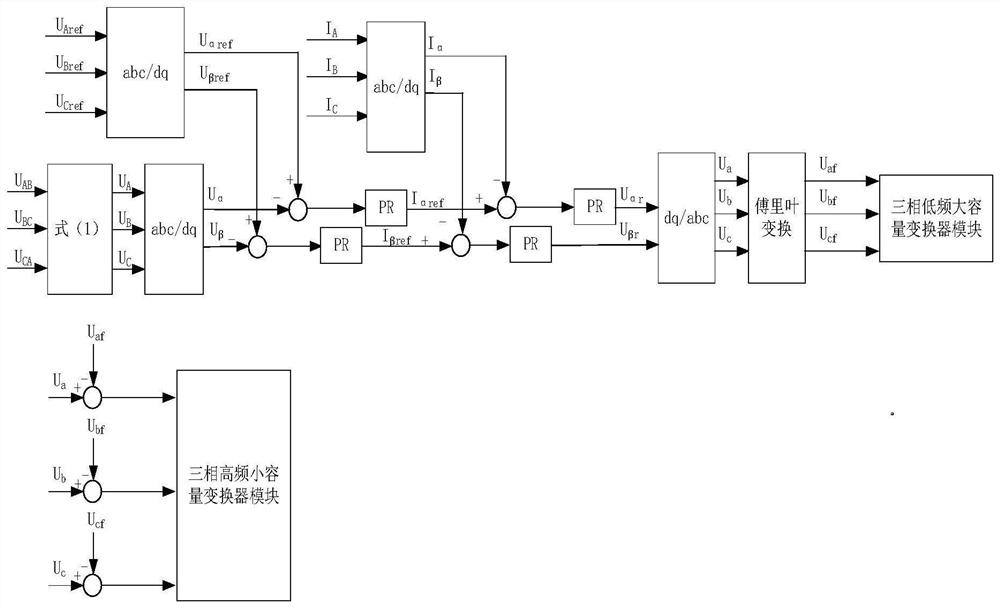
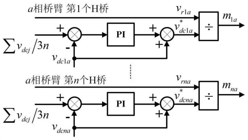
The invention discloses a power grid simulator topological structure and a control method thereof. The topological structure comprises an A phase, a B phase, a C phase, an A phase LC filter, a B phase LC filter and a C phase LC filter, an A phase transformer, a B phase transformer and a C phase transformer and a load, wherein the A phase, the B phase and the C phase are identical in structure. A simulator can operate in a four-quadrant mode, feedback of electric energy to a power grid is achieved, three-phase power grid voltage output can be provided, and various power grid fault conditions such as voltage drop, frequency deviation, three-phase imbalance and harmonic distortion of the power grid can be simulated. On the level of designing the controller, the control mode of the power grid simulator is divided into fundamental wave control and harmonic wave control, namely, a low-frequency large-capacity module and a high-frequency small-capacity module are controlled respectively. In addition, a direct current side voltage follow-up control strategy is provided to solve the problem of power mismatching among modules.

Description

technical field [0001] The invention belongs to the field of power electronic converters and their control, and in particular relates to a network simulator topology and a control method thereof. Background technique [0002] In order to connect distributed power generation systems such as photovoltaics and wind power to the grid, it is necessary to perform a grid adaptability test before grid integration. However, since the grid is a huge system, it is difficult to perform a grid adaptability test. And the main function of the power grid is to provide users with standard three-phase sinusoidal voltage, and various forms of power grid faults are not common. Specialized equipment is therefore required to simulate grid faults and test distributed generation systems. The function of the power grid simulator is to simulate various faults in the output power grid. It can not only output normal grid voltage, but also simulate common faults such as voltage drop, three-phase unbala...

Claims


Application Information

Patent Timeline
Patent Type & Authority Applications(China)
IPC IPC(8): H02M5/42H02M5/458G01R31/00G01R31/08
CPCH02M5/42H02M5/4585G01R31/00G01R31/086Y02E40/40
Inventor 周连俊汪诚彭子琦顾伟峰应展烽殷明慧杨炯明彭云卜京陈载宇邹云
Owner JIANGSU GOLDWIND SCI & TECH CO LTD
Learn More