Eureka AIR delivers breakthrough ideas for toughest innovation challenges, trusted by R&D personnel around the world.

Micro-bubble axial flow and swirl double-field three-stage tube type T-type degassing device

A degassing device and micro-bubble technology, applied in the general layout of liquid degassing, liquid degassing, and production of fluids, etc., can solve problems such as deterioration of separation performance

Active Publication Date: 2022-05-17
QINGDAO TECHNOLOGICAL UNIVERSITY
View PDF0 Cites 0 Cited by
  • Summary
  • Abstract
  • Description
  • Claims
  • Application Information

AI Technical Summary

Problems solved by technology

[0005] Movafaghian et al. carried out research work on the geometric structure, material characteristics, and pressure factors of the columnar gas-liquid separator. The columnar gas-liquid separator (GLCC) is a cyclone gas-liquid separator, and its research and application are the most mature. The working mechanism of the flow gas-liquid separator is mainly to separate the gas and liquid through the conversion of the flow pattern at the inlet and the swirling flow in the cylinder. However, when applied to mist flow and slug flow conditions with high gas-liquid ratio and high gas velocity, the liquid phase will climb up the separator wall in the form of high-speed rotating droplets or liquid film, and finally spin out Trachea, causing deterioration of separation performance
Finally, it should be pointed out that the domestic research on compact and efficient gas-liquid separation technology is still in the experimental stage.

Method used


Image

  • Micro-bubble axial flow and swirl double-field three-stage tube type T-type degassing device
  • Micro-bubble axial flow and swirl double-field three-stage tube type T-type degassing device
  • Micro-bubble axial flow and swirl double-field three-stage tube type T-type degassing device

Examples


Embodiment Construction

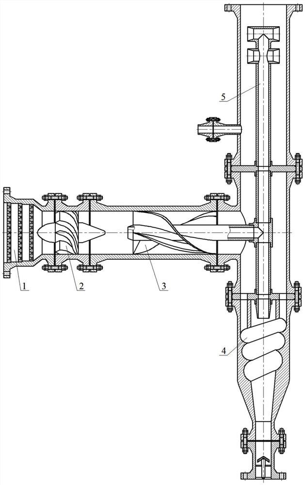
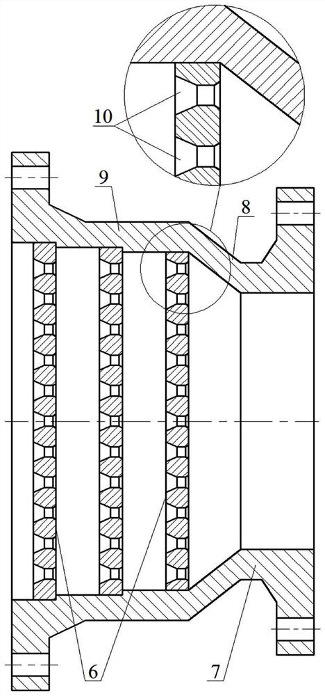
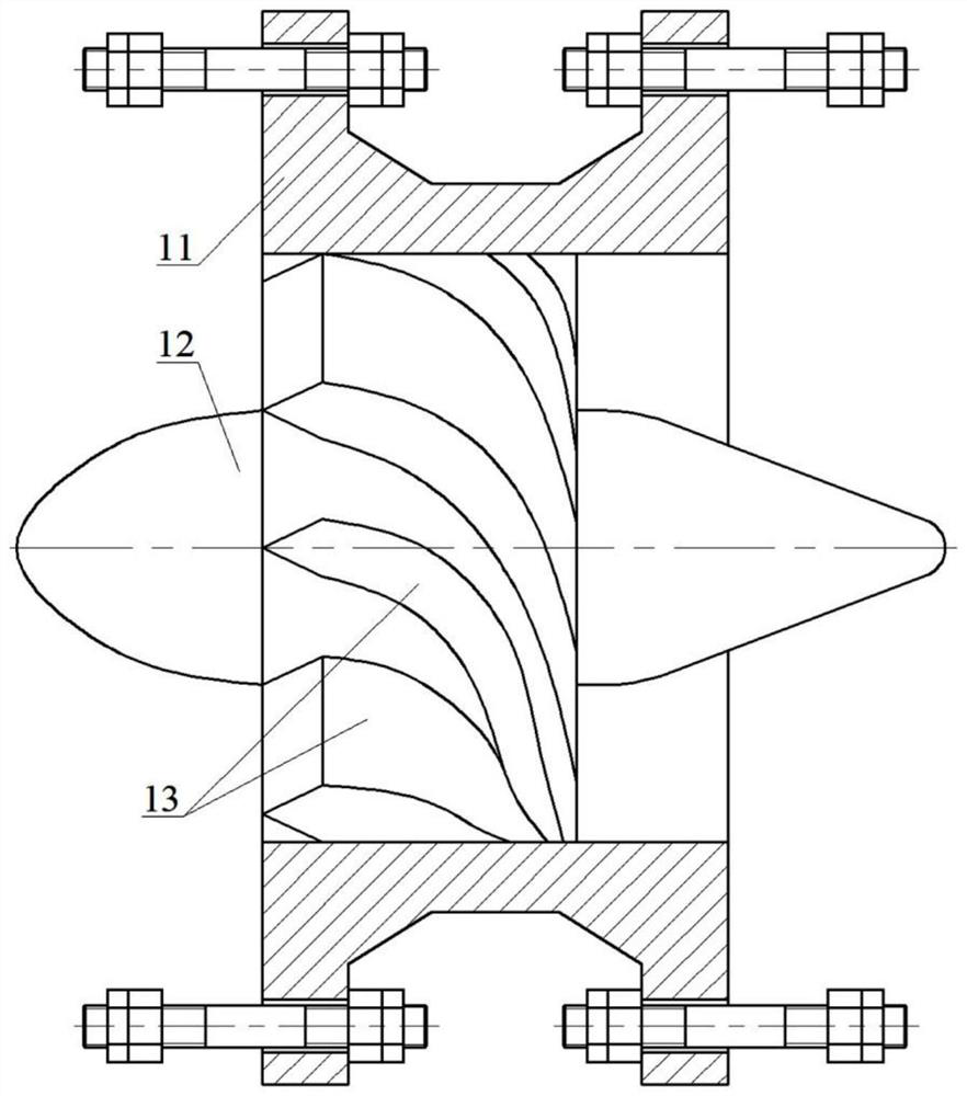
[0046] exist figure 1Among them, the micro-bubble axial flow and swirl double-field three-stage T-type degasser consists of a micro-bubble homomixer 1, a micro-bubble cyclone generator 2, a rotating axial flow degasser 3, and a conical cyclone degasser 4 and jet flow reversing degasser 5, which adopts the rapid degassing technology combining the micro-bubble homogeneous rotating axial flow field and the conical swirling flow field of the spiral channel with the stratified jet collision and reversing degassing. Micro-bubble homogeneous mixing and splitting rotating axial flow degassing operation, vertical spiral channel single-strand conical swirling degassing operation and vertical layered jet collision reversing degassing operation, reversing of jet reversing degasser 5 The buffer column tube body is connected to the gas delivery pipe sink through a flange, and the degassed reversing gas is pressurized and then exported. The reversing liquid discharge pipe is connected to th...


PUM


Abstract

The invention provides a three-stage tube-type T-type degassing device with micro-bubble axial flow and swirl flow, which is applied to the rapid degassing of gas-liquid two-phase flow. The three-stage tubular T-type degassing device adopts the rapid degassing technology combining the micro-bubble homogeneous rotating axial flow field and the conical swirling field of the spiral channel with the stratified jet collision and reversing deep degassing. The gas-liquid two-phase flow containing large bubbles is adjusted to a microbubble homogeneous axial flow, and the microbubble swirler adjusts the microbubble homogeneous axial flow to a split rotating axial flow containing microbubbles, and the rotating axial flow degasser implements Horizontal micro-bubble homogeneous mixing split-share rotary axial flow degassing operation, remove most of the micro-bubbles to form axial flow gas and axial flow liquid, conical swirl degasser implements vertical spiral channel single-strand conical swirl Degassing operation, removing the remaining small amount of micro-bubbles to form swirling gas and swirling liquid, jet flow reversing degasser implements vertical layered jet collision reversing degassing operation, removing small-sized droplets to form reversing Gas and reversing liquid.

Description

technical field [0001] The invention relates to a tubular rapid degassing device in the field of oil and gas field development and exploitation engineering, in particular to a double-field three-stage tubular T-type device combined with a microbubble homogeneous rotating axial flow field and a spiral flow channel conical swirling field. Degassing device and its working process. Background technique [0002] The high-efficiency separation technology of gas-liquid two-phase flow has very important practical significance for oil and gas field development and production engineering. Second, because the high-efficiency degassing technology can effectively reduce the bottom hole back pressure in the process of oil and gas field production, thereby improving oil and gas recovery. [0003] The conventional gas-liquid separation technology uses a container-type separator or a container-type condensate collector. The container-type separator mainly relies on the density difference be...

Claims


Application Information

Patent Timeline
Patent Type & Authority Patents(China)
IPC IPC(8): B01D19/00E21B43/34
CPCB01D19/0057B01D19/0047E21B43/34B01D19/0068
Inventor 刘新福郝忠献陈基余潮泳于广海郝爱刚吴晓明王建峰邢雯石永军王筱磊张瑞强
Owner QINGDAO TECHNOLOGICAL UNIVERSITY
Why Eureka
Eureka Blog
Learn More