
Building wall grooving device

A wall and building technology, applied in the field of building wall slotting devices, can solve the problems of cutting blade loss, worker injury, and inconvenient cleaning for workers, and achieve the effects of avoiding loss, increasing speed, and reducing use costs

Active Publication Date: 2021-06-04
华晟工程技术有限公司
View PDF12 Cites 0 Cited by
  • Summary
  • Abstract
  • Description
  • Claims
  • Application Information

AI Technical Summary

Problems solved by technology

[0007] The object of the present invention is to provide a slotting device for building walls, to solve the above-mentioned problems in the background technology that workers generally need to carry out slotting on the wall. Because the slotting device is generally heavy in weight, it is easy for workers to use it for a long time. Insufficient physical strength makes the grooving device let go of the hands, which will cause injury to the workers, and the grooving may not be neat and beautiful because the workers hold it in their hands. Generally, the cutting blades are replaced when grooving different depths of grooves, which is easy to cause certain damage to the progress of the workers' decoration. Influenced by the impact, and the replacement of the cutting piece is easy to cause loss, which increases the user's use cost to a certain extent. Generally, a large amount of dust is likely to be generated when cutting the wall, which will cause great damage to the subsequent cleaning of the workers. It is inconvenient, and the flying dust is easily inhaled by the workers to cause harm, and it will also have a certain impact on the cutting line of sight of the workers

Method used


Image

  • Building wall grooving device
  • Building wall grooving device
  • Building wall grooving device

Examples


Embodiment Construction

[0030] The following will clearly and completely describe the technical solutions in the embodiments of the present invention with reference to the accompanying drawings in the embodiments of the present invention. Obviously, the described embodiments are only some, not all, embodiments of the present invention. Based on the embodiments of the present invention, all other embodiments obtained by persons of ordinary skill in the art without making creative efforts belong to the protection scope of the present invention.

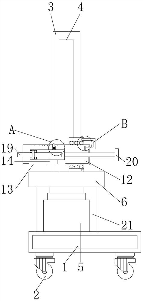
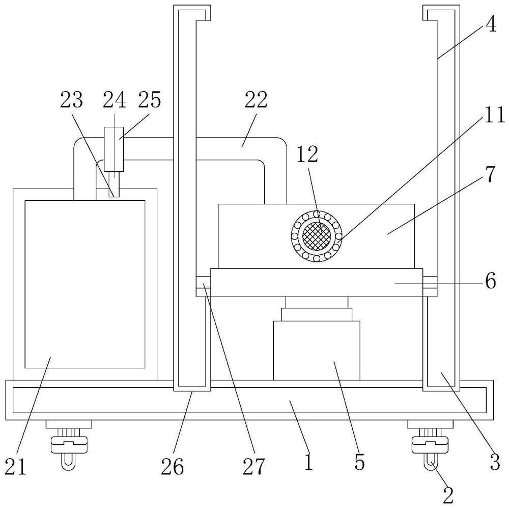
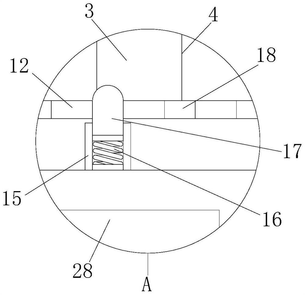
[0031] see Figure 1-7, the present invention provides a technical solution: a building wall slotting device, including a bottom plate 1, a universal wheel 2, a fixed bracket 3, a first chute 4, an electric push rod 5, a top plate 6, a fixed plate 7, and a first card slot 8, card rod 9, limit plate 10, bearing 11, outer shell 12, second chute 13, special-shaped slider 14, guide plate 15, limit spring 16, circular limit block 17, limit hole 18, Cutting piece 1...


PUM


Abstract

The invention discloses a building wall grooving device which comprises a bottom plate, a fixing plate and a banister brush, wherein universal wheels are fixedly connected to the bottom of the bottom plate, a third clamping groove is formed in the top of the bottom plate, a fixing support is fixedly mounted on the inner wall of the third clamping groove, and a first sliding groove is formed in the side of the fixing support. According to the building wall grooving device disclosed by the invention, after a grooving depth of a cutting blade is adjusted, a bottom plate is pushed, a grooving machine is moved to the side of a wall through universal wheels, and the grooving machine is started, so that the wall is grooved through the cutting blade, the cutting blade can conduct rotary cutting through an arranged bearing; and through an arranged electric push rod, a top plate slides in the first sliding groove in the side of the fixing support through the T-shaped sliding block to cut the whole wall, so that a worker can groove the wall without holding the grooving device, and the situation that the worker is hurt due to the fact that the grooving device slips out of the hand when the worker holds the grooving device for a long time due to physical strength is avoided, and therefore, grooves formed by workers are attractive and tidy.

Description

technical field [0001] The invention relates to the technical field of slotting devices, in particular to a slotting device for building walls. Background technique [0002] The grooving device is mainly used for repairing asphalt and cement pavement, drainage pipes, gas pipes, electric wire pipes and optical cable pipes. The pavement is quickly cut into uniform grooves by means of a rotary saw to form a new joint surface, optimizing the joint filling material and The contact surface of the slot is to strengthen the tightness of the bonding between the filling material and the side wall of the slot. Since it is necessary to lay pipes or lines into the wall during decoration, it is generally necessary to use a slotting device to slot the building wall , to facilitate the follow-up work of the workers, but there are still certain defects in the existing building wall slotting device, such as: [0003] 1. Existing wall slotting devices for buildings generally require workers t...

Claims


Application Information

Patent Timeline
Patent Type & Authority Applications(China)
IPC IPC(8): B28D1/24B28D7/00B28D7/02
CPCB28D1/24B28D7/005B28D7/00B28D7/02
Inventor 万志芳
Owner 华晟工程技术有限公司
Learn More