Method for recycling steel ladle casting residual steel and casting residual slag

A casting slag and casting slag technology, which is applied in the manufacture of converters, etc., can solve the problems that casting slag and cast steel can not be effectively utilized, and achieve the effects of reducing lime consumption, increasing usage, and reducing consumption

Pending Publication Date: 2021-06-04
南京宝希智能技术有限公司
View PDF5 Cites 0 Cited by
  • Summary
  • Abstract
  • Description
  • Claims
  • Application Information

AI Technical Summary

Problems solved by technology

[0006] Aiming at the problem that casting slag and cast steel cannot be effectively utilized in the prior art, the present invention provides a recycling method for ladle cast steel and cast slag;

Method used


Image

  • Method for recycling steel ladle casting residual steel and casting residual slag
  • Method for recycling steel ladle casting residual steel and casting residual slag
  • Method for recycling steel ladle casting residual steel and casting residual slag

Examples


Embodiment 1

[0044] In this example, the tapping temperature is 1640°C, the cast steel temperature is 1550°C, the scrap steel temperature is 25°C, the ore temperature is 25°C, and the molten iron temperature is 1250°C. Therefore, the cooling energy of each component is shown in Table 2. , where the cooling energy refers to the ratio of the heat absorbed by the material to the scrap steel.

[0045] The starting temperature, tapping temperature, heat absorption and cooling energy of each component in Table 2

[0046] Material Cast steel molten iron ore scrap steel start temperature 1550 1250 25 25 Physical heat, kJ.kg -1

1342.53 1145.44 0 -1417.86 Element oxidation heat release, kJ.kg -1

986.47 Decomposition heat, kJ.kg -1

-4323.8 Heat energy, kJ.kg -1

1342.53 2131.91 -4323.8 -1417.86

[0047] Note: "+" means converter heat income, "-" means converter heat expenditure.

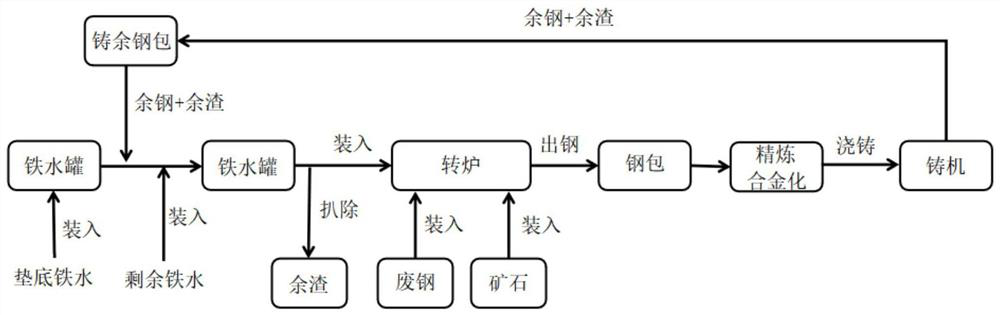
[0048] Such as figure 1 As show...

Embodiment 2

[0070] This embodiment provides a method for recycling ladle cast steel and cast slag, which is basically the same as that of Example 1, the difference being that the cast steel is used to replace scrap steel, since the scrap steel contains 8%- About 9% impurities, use 1 ton of cast steel, correspondingly reduce 1.10 to 1.15 tons of scrap steel. Since every 1 ton of excess cast steel is increased, 1.10t of scrap steel loading can be reduced correspondingly, and the corresponding heat can increase the ore amount by 0.67t (=(heat energy of cast excess steel-conversion ratio of cast excess steel*scrap heat energy) / ore Heat energy=(1342.53-(-1417.86)*1.1) / 4323.8=0.67). Since other conditions are almost unchanged, the removal rate of P and S in the bottom molten iron by casting slag is basically the same as that of Example 1, and the difference mainly lies in the amount of steel tapped in each furnace.

[0071] The charging method adopted in this embodiment is: total charging amou...


PUM


Abstract

The invention discloses a method for recycling steel ladle casting residual steel and casting residual slag, and belongs to the technical field of steel and iron smelting. The method comprises the following steps that casting residual steel and casting residual slag are loaded into a molten iron tank containing bottom molten iron; and a temperature of the casting residual steel and the casting residual slag is not lower than 1500 DEG C, and in the bottom molten iron, a content of P ranges from 0.100 wt% to 0.150 wt% and a content of S ranges from 0.020 wt% to 0.060 wt%. According to the method, direct recycling of heat of the casting residual steel and the casting residual slag can be achieved, meanwhile, when the bottom molten iron makes contact with the casting residual steel, the casting residual slag also enters the bottom molten iron, harmful elements S and P in part of the molten iron can be removed by means of the high-alkalinity casting residual slag under a stirring effect, and lime consumption for converter smelting is reduced.

Description

technical field [0001] The invention belongs to the technical field of iron and steel smelting, and more specifically relates to a recycling method for ladle cast steel and cast slag. Background technique [0002] In the converter-casting machine process, in addition to the molten steel, there is slag in the ladle containing the molten steel. The main source of the slag is the slag during the tapping process of the converter, the added alloy element oxides, and the refining slag such as lime. material. In order to ensure the quality of the slab, generally when there is a certain amount of molten steel in the ladle, the ladle withdraws from the casting process to ensure that the steel slag in the ladle does not enter the tundish. The remaining molten steel and slag in the ladle are poured out through the slag basin, cooled together with ordinary steel slag, and the iron balls are selected by magnetic separation in the steelmaking slag turning process, and enter the converter...

Claims


Application Information

Patent Timeline
IPC IPC(8): C21C5/28
CPCC21C5/28C21C2200/00
Inventor 占小立
Owner 南京宝希智能技术有限公司
Why Eureka
Try Eureka