Yarn waxing machine facilitating rapid waxing and used for spinning

A yarn and wax machine technology, used in textiles and papermaking, can solve problems such as affecting the efficiency of yarn waxing, unable to ensure the continuity of equipment work, avoiding free rotation, ensuring stability, and improving work efficiency. Effect

Pending Publication Date: 2021-06-04
黄招
View PDF1 Cites 2 Cited by
  • Summary
  • Abstract
  • Description
  • Claims
  • Application Information

AI Technical Summary

Problems solved by technology

[0006] In order to overcome the disadvantages that the existing waxing machine needs to be shut down to replace the wax block, the continuity of the equipment cannot be guaranteed, and the work efficiency of waxing the yarn is affected, the technical problem to be solved by the present invention is to provide a non-stop machine. Replace the wax blocks to ensure the continuity of waxing on the yarn and improve work efficiency. The yarn waxing machine for textiles that is easy to wax quickly

Method used


Image

  • Yarn waxing machine facilitating rapid waxing and used for spinning
  • Yarn waxing machine facilitating rapid waxing and used for spinning
  • Yarn waxing machine facilitating rapid waxing and used for spinning

Examples


Embodiment 1

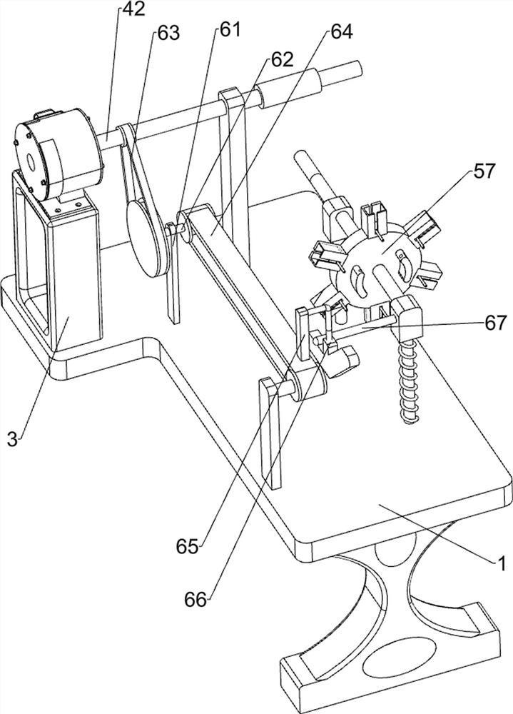
[0031] A kind of yarn waxing machine that is convenient for fast waxing for weaving, such as Figure 1 to Figure 5 As shown, it includes a base 1, a material guide plate 2, a support 3, a driving mechanism 4, a wax release mechanism 5, a transmission mechanism 6 and a telescopic mechanism 7. The top of the base 1 is connected with a material guide plate 2 in the middle, and the top of the base 1 The rear side is connected with a support 3, a drive mechanism 4 is connected between the support 3 and the base 1, a wax discharge mechanism 5 is installed in the middle of the top of the base 1, and a transmission mechanism 6 is connected between the drive mechanism 4 and the wax discharge mechanism 5. The wax release mechanism 5 is connected with a telescopic mechanism 7 .

[0032] The driving mechanism 4 includes a motor 41, a first shaft rod 42, a first fixed plate 43, a second fixed plate 44 and a first fixed rod 45. The top of the support 3 is connected to the motor 41, and the ...

Embodiment 2

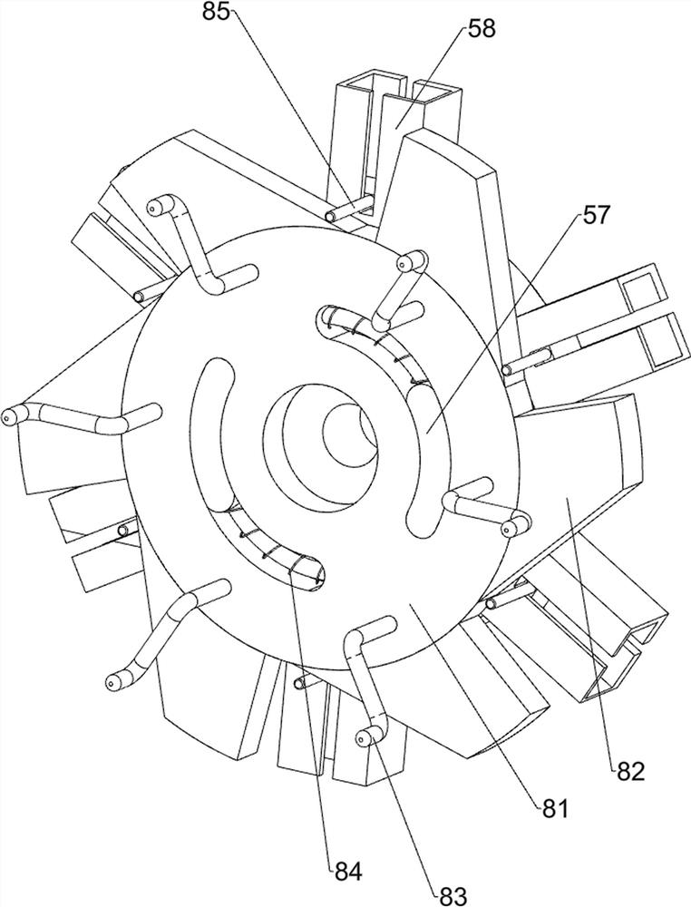
[0038] On the basis of Example 1, such as Figure 6 and Figure 7 As shown, it also includes a wax removal mechanism 8, and the wax removal mechanism 8 includes a second disc 81, a second inclined block 82, a Z-shaped rotating rod 83, an arc spring 84 and a contact rod 85, and the first disc 57 is rotatably connected with a second disc 81, and the second disc 81 is connected with second oblique blocks 82 equal in number to the number of wax-discharging tanks 58 at even intervals around the second disc 81, and the sides of the second disc 81 are evenly spaced. The ground is connected with a Z-shaped rotating rod 83, an arc spring 84 is connected between the first disk 57 and the second disk 81, and a contact rod 85 is connected on each sliding plate 59, and the contact rod 85 and the second oblique Block 82 is a contact fit.

[0039] When all the wax pieces in the wax putting tank 58 are used up and need to be replaced, the Z-shaped rotating rod 83 is manually rotated, and th...

Embodiment 3

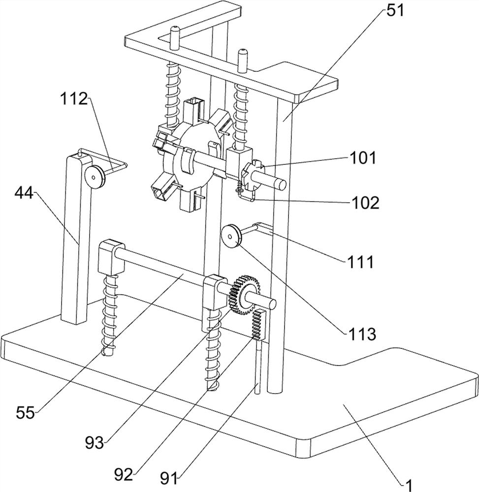
[0043] On the basis of Example 2, such as Figure 7 As shown, it also includes a limit mechanism 10. The limit mechanism 10 includes a sheave 101 and an elastic matching rod 102. The right part of the second shaft rod 55 on the upper and lower sides is connected with a sheave 101, and the first fixed block 54 is connected with a sheave 101. There is an elastic fitting rod 102 that cooperates with the sheave 101 .

[0044] When the second shaft 55 rotates, the sheave 101 rotates accordingly, and the sheave 101 rotates to forcibly push the elastic fitting rod 102 away. When the next slot of the sheave 101 is aligned with the elastic fitting rod 102, the elastic fitting rod 102 is snapped into the draw-in groove of the sheave 101, so that the sheave 101 can be fixed, avoiding the free rotation of the second axle rod 55, and ensuring the stability of the equipment when waxing.

[0045] Also includes a positioning assembly 11, the positioning assembly 11 includes a first connectin...


PUM


Abstract

The invention relates to a yarn waxing machine, in particular to a yarn waxing machine facilitating rapid waxing and used for spinning. The yarn waxing machine facilitating rapid waxing and used for spinning can replace wax blocks without shutdown, guarantees the continuity of yarn waxing and improves the working efficiency. For solving the technical problem, the invention provides the yarn waxing machine facilitating rapid waxing and used for spinning. The yarn waxing machine comprises a base provided with a material guide plate connected to the middle of the top, a support connected to the top of the base, a driving mechanism mounted between the support and the base, a wax placing mechanism connected to the top of the base, and a transmission mechanism connected between the driving mechanism and the wax placing mechanism. According to the yarn waxing device, yarn can be waxed through the driving mechanism, the wax placing mechanism, the transmission mechanism and the telescopic mechanism, the multiple wax blocks can be switched for use, and the wax blocks do not need to be manually and frequently replaced.

Description

technical field [0001] The invention relates to a yarn waxing machine, in particular to a yarn waxing machine which is convenient for fast waxing for textile use. Background technique [0002] Textile machinery is the production means and material basis of the textile industry. Its technical level, quality and manufacturing cost are directly related to the development of the textile industry. Textile machinery is widely used in the textile industry. In actual production, it is necessary to wax the yarn. The effect of waxing the yarn is closely related to the waxing equipment. [0003] After searching, the patent publication number is: CN106048795A patent discloses a kind of cleaning type textile yarn waxing mechanism, which includes a frame, and is characterized in that: the frame is provided with a waxing assembly and a thread transmission assembly, so The above-mentioned waxing assembly includes vertical plates arranged on both sides of the frame. The adjacent sides of th...

Claims


Application Information

Patent Timeline
Patent Type & Authority Applications(China)
IPC IPC(8): D02J3/18
CPCD02J3/18
Inventor 黄招
Owner 黄招
Why Eureka
Try Eureka