Equipment fault prediction method and system

A prediction method and fault prediction technology, applied in the direction of instruments, biological neural network models, character and pattern recognition, etc., can solve the problems of heavy workload in factory network layout, inability to specifically locate equipment failures, and inability to classify equipment damage levels, etc., to achieve The effect of improving the task success rate, improving the equipment integrity rate, and shortening the maintenance time

Pending Publication Date: 2021-06-04
深圳市芯聚智科技有限公司
View PDF0 Cites 3 Cited by
  • Summary
  • Abstract
  • Description
  • Claims
  • Application Information

AI Technical Summary

Problems solved by technology

[0012] 1. Mainly by using the past, present and future information about the equipment environment, operation and use status to detect equipment degradation, diagnose its damage, and predict and diagnose faults. The equipment environment information is mainly obtained through various sensors and equipment Relevant system indicators are obtained, such as vibration, temperature, pressure, etc. These indicators can usually reflect the indirect state of the equipment, and there may be delays or even failures
At the same time, due to the use of equipment system indicators, only equipment failures can be detected, but the specific location of the equipment failure cannot be specifically located, and the damage degree of the equipment cannot be classified, which is not conducive to the location of equipment failures
[0013] 2. The current fault detection system mainly collects system data through sensors and transmits it to the central computer for processing. Some even collect data during work, and perform offline processing during night shutdown. Since data processing is far away from the industrial equipment itself, a On the one hand, it will cause the problem of untimely information processing; on the other hand, it will cause the problem of heavy workload in modifying the existing factory network layout
[0014] 3. The specific structure of the neural network is often not introduced in the existing technical materials, but in practice, different network structures have a huge impact on the prediction results, and a lot of refinement of the specific network is required in the fault prediction settings

Method used


Image

  • Equipment fault prediction method and system
  • Equipment fault prediction method and system
  • Equipment fault prediction method and system

Examples


Embodiment Construction

[0044] In order to illustrate the present invention more clearly, relevant concepts and definitions are explained first.

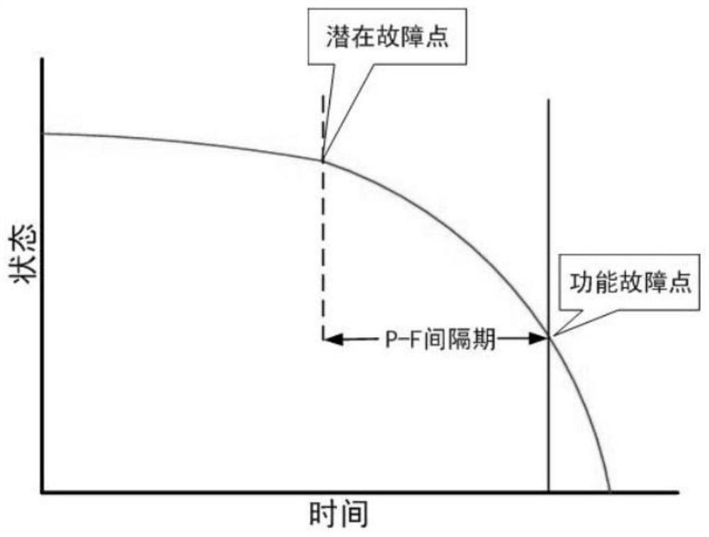
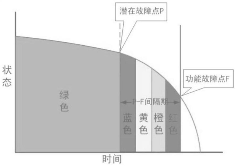
[0045] The prerequisite for fault prediction is that for some faults, the performance degradation is a gradual degradation process, that is, there is a "potential fault-functional fault" interval, such as figure 1As shown, this process is also the P-F interval. The "P" point is a potential fault point, which is the point where the fault can be found. Before that, the fault does not have any symptoms. Regression to point of functional failure "F", i.e. the device is no longer usable. The existence of "PF interval" is a prerequisite for prediction of complex equipment, that is, state-based AI prediction is only applicable to faults with "PF interval". Equipment performance is also a process of gradual degradation. After a certain time point (potential failure point "P"), alarm information and log information will be generated, and the performance will begi...


PUM


Abstract

The invention discloses an equipment fault prediction method. The method comprises the following steps: training is performed by an key component image training sample of equipment; an input training sample set is trained, the training sample set comprises output data of the Bayesian network model and training samples containing a plurality of working parameters, and a neural network model is obtained through training according to the training sample set; an acquisition module acquires working state data of the equipment; a key component image of the equipment is acquired; the obtained image of the key component into a Bayesian network model is input to output data DIA; the working state data of the equipment is preprocessed to obtain data DIB and fault prediction is made by using DIA and DIB according to the neural network model. Fault occurrence prediction and fault occurrence position locking can be provided, so that production loss is reduced, maintenance support cost is reduced, and the equipment perfectness rate and the task success rate are improved; through state monitoring, risks caused by faults in the task process are reduced, and the task success rate is improved.

Description

technical field [0001] The invention relates to the field of fault diagnosis and prediction of industrial production equipment, in particular to a neural network-based equipment fault prediction system and method Background technique [0002] Traditional industrial production equipment will be subject to continuous vibration and shock during continuous work, coupled with temperature and wear, which will lead to wear and aging of equipment materials and parts, resulting in industrial equipment prone to failure, and when the failure is realized, it may have already Many defective products have been produced, and even the entire industrial equipment has collapsed and shut down, resulting in huge losses. If the failure prediction can be made before the failure occurs, and the parts that are about to have problems can be repaired and replaced in advance, the service life of the equipment can be improved and the sudden failure of a certain equipment can be prevented from seriously...

Claims


Application Information

Patent Timeline
Patent Type & Authority Applications(China)
IPC IPC(8): G06K9/62G06N3/04
CPCG06N3/044G06N3/045G06F18/24155G06F18/214
Inventor 欧阳鹏朱真杨传雷邓辉
Owner 深圳市芯聚智科技有限公司
Why Eureka
Try Eureka