Mutual inductor with stable fixing structure

A fixed structure and transformer technology, applied in transformer/inductor magnetic core, transformer/inductor cooling, transformer/inductor shell, etc., can solve the problem of increased difficulty of transformer installation, reduced circuit connection stability, and transformer Problems such as spacing distance adaptation, to achieve the effect of improving the fixed range of installation, improving stability, and improving installation efficiency

Active Publication Date: 2021-06-04
STATE GRID ZHEJIANG ELECTRIC POWER COMPANY TAIZHOU POWER SUPPLY
View PDF8 Cites 0 Cited by
  • Summary
  • Abstract
  • Description
  • Claims
  • Application Information

AI Technical Summary

Problems solved by technology

[0003] The two sets of coils on the transformer are used to connect different circuits, so that the transformer cannot be adapted to the distance between adjacent circuits during actual installation, which makes the installation of the transformer in adjacent circuits more difficult. At the same time, the existing transformer terminal lacks a fixing device when it is connected to the circuit, and the single connection terminal socket is easy to fall off during the actual test, resulting in a decrease in the stability of the circuit connection
[0004] For this purpose, a transformer with a stable fixed structure is provided to solve the installation and connection problems of the transformer between adjacent circuits

Method used


Image

  • Mutual inductor with stable fixing structure
  • Mutual inductor with stable fixing structure
  • Mutual inductor with stable fixing structure

Examples


Embodiment Construction

[0024] The following will clearly and completely describe the technical solutions in the embodiments of the present invention with reference to the accompanying drawings in the embodiments of the present invention. Obviously, the described embodiments are only some, not all, embodiments of the present invention. Based on the embodiments of the present invention, all other embodiments obtained by persons of ordinary skill in the art without making creative efforts belong to the protection scope of the present invention.

[0025] see Figure 1 to Figure 3 , the present invention provides a technical solution:

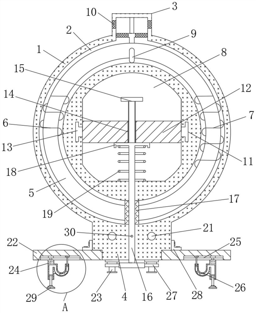
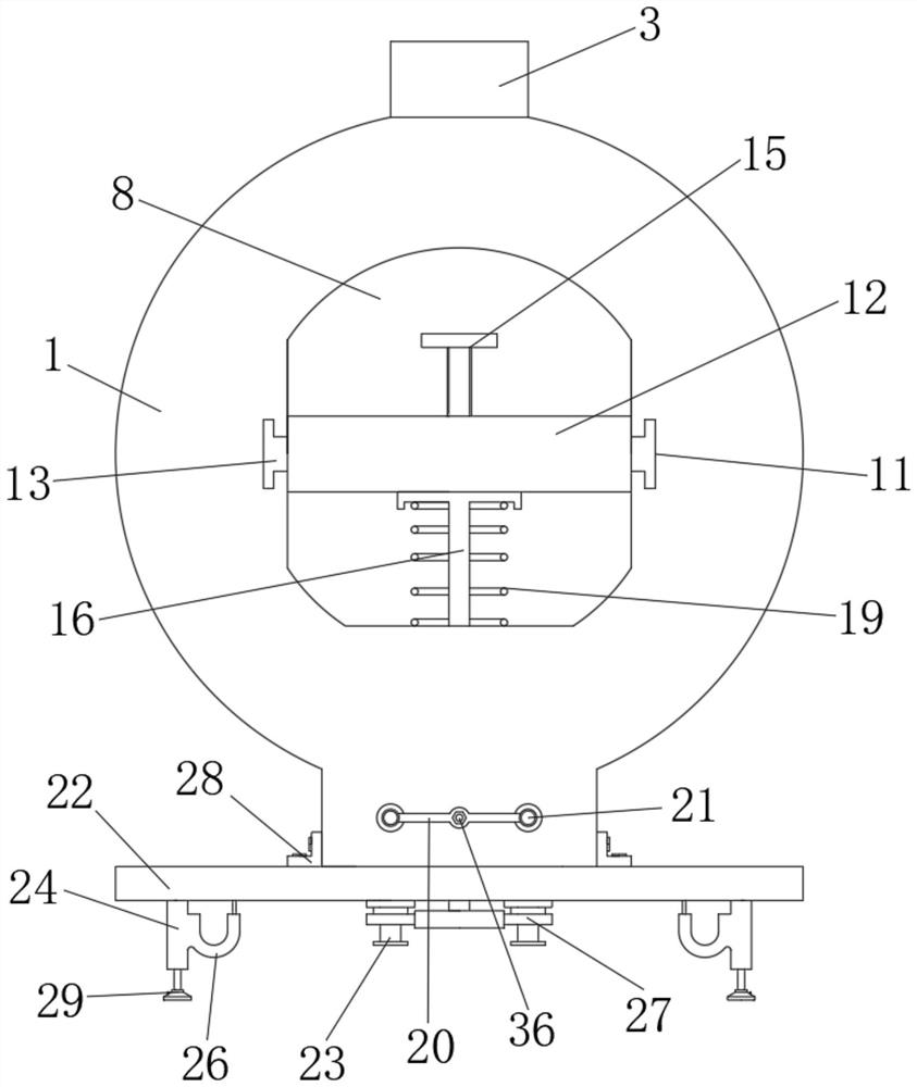
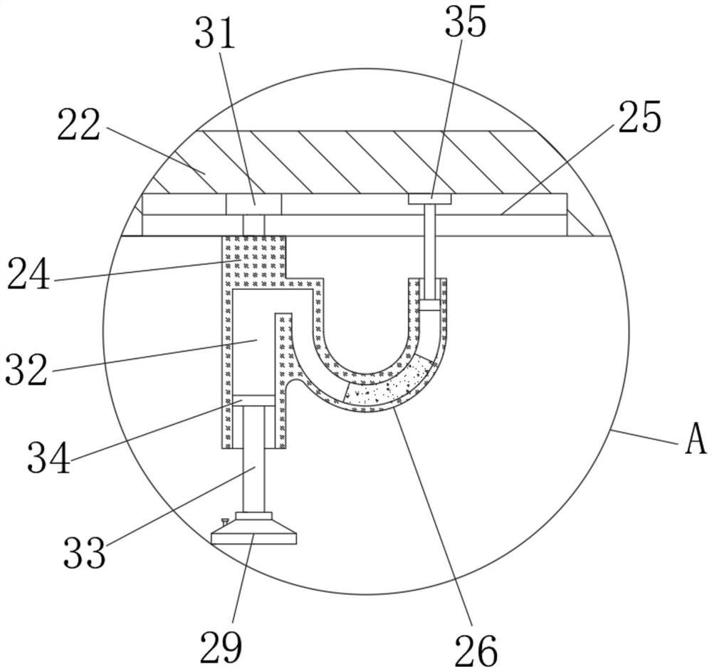
[0026] A transformer with a stable fixed structure, comprising a transformer shell 1, the ring cavity of the transformer shell 1 is set as an installation cavity 2, and a mutual induction core 5 is arranged inside the installation cavity 2, and the transformer shell 1 is provided with a cooling boss 3 in the middle of the upper end, the upper end of the hook 9 is fixed o...


PUM


Abstract

The invention relates to the technical field of mutual inductor installation, in particular to a mutual inductor with a stable fixing structure. The mutual inductor comprises a mutual inductor shell, a circular ring inner cavity of the mutual inductor shell is set as an installation inner cavity, a heat dissipation boss is arranged in the middle of the upper end of the mutual inductor shell, and a plugging base is arranged at the lower end of the mutual inductor shell. The mutual inductor has the beneficial effects that by arranging the sliding mounting block, the left and right mounting and fixing positions are matched with the interval between the adjacent circuits, the mounting and fixing range of the mutual inductor is widened, the mounting stability of the mutual inductor is greatly enhanced, and meanwhile, the pressing change of a U-shaped pipe is utilized to realize extrusion and fixation of the sliding position; through the cooperation of the pull rod and the plugging frame, the connection position of the binding post is pressed and fixed, so that the stability of circuit connection is improved, through the cooperation of the extrusion screw rod and the locking nut, the wiring position is conveniently disassembled, and the installation efficiency of the mutual inductor is greatly improved.

Description

technical field [0001] The invention relates to the technical field of transformer installation, in particular to a transformer with a stable fixed structure. Background technique [0002] Transformer, also known as instrument transformer, is a general term for current transformer and voltage transformer. It can change high voltage into low voltage and high current into small current for measurement or protection system. Its function is mainly to convert high voltage or high current into standard low voltage (100V) or standard small current (5A or 1A, both refer to rated value) in proportion, so as to realize the standardization and miniaturization of measuring instruments, protection equipment and automatic control equipment. change. [0003] The two sets of coils on the transformer are used to connect different circuits, so that the transformer cannot be adapted to the distance between adjacent circuits during actual installation, which makes the installation of the tran...

Claims


Application Information

Patent Timeline
Patent Type & Authority Applications(China)
IPC IPC(8): H01F27/06H01F27/29H01F27/30H01F27/26H01F27/02H01F27/08
CPCH01F27/06H01F27/29H01F27/306H01F27/266H01F27/025H01F27/085
Inventor 卢益宝
Owner STATE GRID ZHEJIANG ELECTRIC POWER COMPANY TAIZHOU POWER SUPPLY
Why Eureka
Try Eureka