Visible light communication meniscus lens antenna for miniaturization of transceiver and its design method

A visible light communication and meniscus lens technology, applied in the fields of visible light communication and optical antennas, can solve the problems of high system complexity, high implementation cost, large imaging size, and increased system deployment cost, so as to reduce implementation complexity and deployment cost, and improve the The effect of robustness

Active Publication Date: 2022-05-13
UNIV OF SCI & TECH OF CHINA
View PDF8 Cites 0 Cited by
  • Summary
  • Abstract
  • Description
  • Claims
  • Application Information

AI Technical Summary

Problems solved by technology

However, these two implementation schemes have certain limitations. Scheme 1 has a large imaging size during long-distance imaging, so the size of the optical module at the receiving end is correspondingly large and difficult to miniaturize. At the same time, multi-color multiplexing requires the use of multiple optical filters. chip, which also increases the cost of system deployment; in solution 2, when using RGBY four colors to realize parallel high-speed visible light communication, it is necessary to use three dichroic mirrors at the transceiver end, the system complexity and implementation cost are high, and the system is also difficult miniaturization problem

Method used


Image

  • Visible light communication meniscus lens antenna for miniaturization of transceiver and its design method
  • Visible light communication meniscus lens antenna for miniaturization of transceiver and its design method
  • Visible light communication meniscus lens antenna for miniaturization of transceiver and its design method

Examples


Embodiment

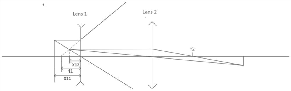
[0036] One implementation of high-speed visible light communication is multi-color parallel visible light communication. However, the existing multi-color parallel visible light communication systems all face problems such as complex system structure, high deployment cost, and difficulty in miniaturization. Therefore, a transmit optical antenna design based on a concave-convex lens combination is proposed, which can realize the miniaturization of the system and reduce the complexity of the system under the premise of meeting the power requirements of the receiver. The lens types used in actual deployment are shown in Table 1.

[0037] Table 1

[0038] lens diameter / mm Focal length / mm shape model L1 25.4 50 biconcave lens LD1464-A L2 75.0 100 plano-convex LA1238-A

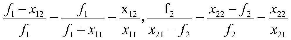
[0039] In actual deployment, first adjust the distance x from the object to the first-stage lens 11 , so that a reduced virtual image of appropriate size is formed between ...


PUM


Abstract

The present invention proposes a visible light communication concave-convex lens antenna and its design method for the miniaturization of the receiving end. By selecting the lens combination and spatial arrangement with appropriate parameters, a clearly separated light spot of reduced size is formed at the receiving end, and then at the receiving end The lens is used to collect and receive the light paths of each color separately, so as to realize parallel high-speed visible light communication. The advantages of the present invention are as follows: firstly, by using the concavo-convex cascaded optical antenna system, the receiving end can form a separated light spot with reduced size, which can effectively realize the miniaturization of the system. Second, parallel communication is realized by independently receiving separated light spots, which avoids the use of dichroic mirrors and optical filters, and effectively reduces the complexity of system implementation and deployment costs. Third, by selecting a lens with reasonable parameters and a spatial layout, we can adjust the imaging size ratio and the specific imaging position, that is, the antenna system can adapt to different application scenarios and has good robustness.

Description

technical field [0001] The invention relates to the technical field of visible light communication and the field of optical antennas, in particular to a visible light communication concave-convex lens antenna and a design method thereof for the miniaturization of the receiving and receiving ends. Background technique [0002] Visible Light Communication (VLC) uses the visible light spectrum for communication. Visible light communication has many advantages such as rich spectrum resources, freedom from electromagnetic interference, safety and reliability, and has been extensively studied in recent years. At present, visible light communication is mainly deployed based on light-emitting diodes (Light Emitting Diode, LED). It has been widely used in many scenarios such as lighting and outdoor LED large screens. LED-based visible light communication can be built on the existing lighting infrastructure, which can greatly reduce the deployment cost and has a good application prosp...

Claims


Application Information

Patent Timeline
Patent Type & Authority Patents(China)
IPC IPC(8): H04B10/116G02B27/09
CPCH04B10/116G02B27/0955
Inventor 于子晨魏佳琦龚晨黄诺徐正元
Owner UNIV OF SCI & TECH OF CHINA
Why Eureka
Try Eureka