Communication system and receiving-side device

A communication system, technology on the receiving side, applied in the directions of synchronization devices, transmission systems, wireless communication, etc., can solve problems such as conflicts

Pending Publication Date: 2021-06-04
MITSUBISHI ELECTRIC CORP
View PDF0 Cites 0 Cited by
  • Summary
  • Abstract
  • Description
  • Claims
  • Application Information

AI Technical Summary

Problems solved by technology

RACH is at risk of conflict

Method used


Image

  • Communication system and receiving-side device
  • Communication system and receiving-side device
  • Communication system and receiving-side device

Examples


Embodiment approach 1

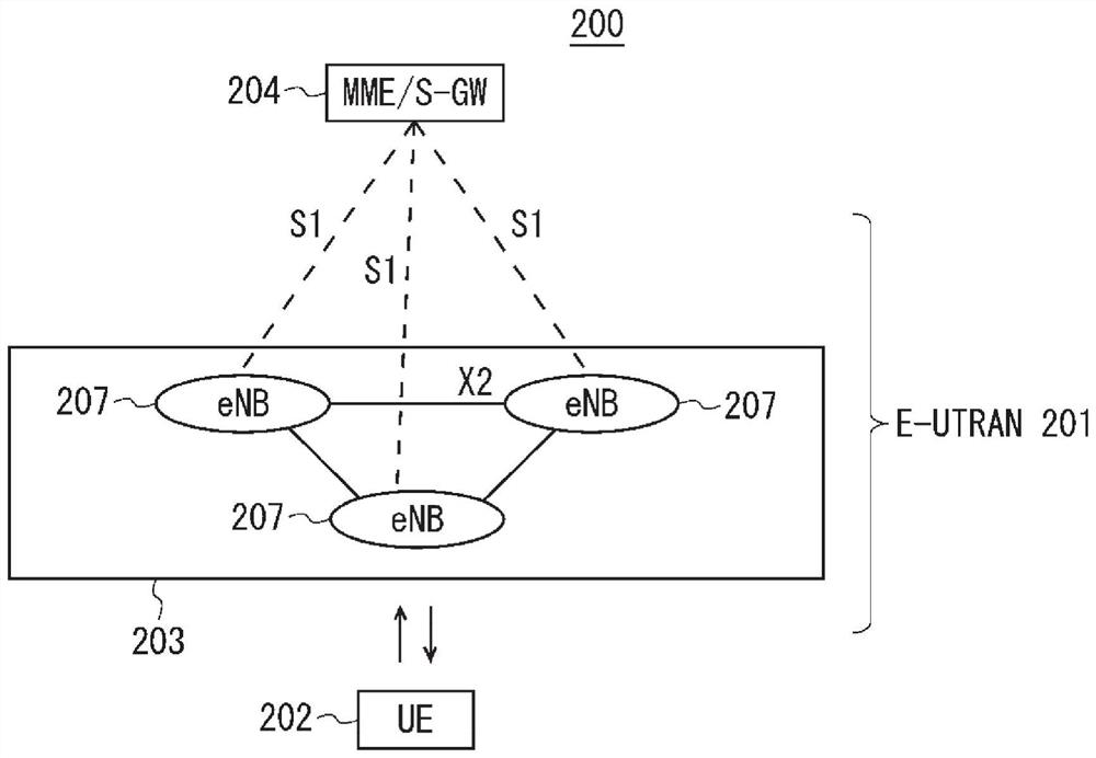
[0136] figure 2 It is a block diagram showing the overall configuration of an LTE-based communication system 200 discussed in 3GPP. right figure 2 Be explained. The radio access network is called E-UTRAN (Evolved Universal Terrestrial Radio Access Network: Evolved Universal Terrestrial Radio Access Network) 201 . A mobile terminal device (hereinafter referred to as "mobile terminal (User Equipment: UE)")_202, which is a communication terminal device, can perform wireless communication with a base station device (hereinafter referred to as "base station (E-UTRAN NodeB: eNB)")_203. Communication performs sending and receiving of signals.

[0137] Here, the "communication terminal device" refers not only to a mobile terminal device such as a mobile phone terminal device but also to non-moving devices such as sensors. In the following description, a "communication terminal device" may be simply referred to as a "communication terminal".

[0138] If the control protocol for ...

example 2

[0357] In Embodiment 1 and Modification 1 of Embodiment 1, the case where packet replication is used is disclosed as an example of a method satisfying URLLC requirements, but repetition (repetition) may also be used.

[0358] However, in the repetition, the HARQ feedback transmission from the receiving side apparatus is performed after the completion of the transmission for a predetermined number of repetitions. As a result, the receiving side apparatus receives data in the middle of the predetermined number of repetitions, and even if it cannot be correctly demodulated and decoded, the receiving side apparatus waits for the remaining number of times of reception before performing HARQ feedback. The same applies to the transfer to the upper layer (for example, RLC) of the received data to the receiving side device. As a result, there is a problem that the delay in the data transmission deteriorates.

[0359] Solutions to the above-mentioned problems are disclosed below.

[0...

Embodiment approach 2

[0469] In the NR cell, the dormant state shown in Non-Patent Document 24 (TS36.321 V15.2.0) can be applied. The UE can use the MAC signaling from the gNB to transfer the communication state with the cell of the gNB to the dormant state, or to the active state.

[0470] However, when a cell configured for packet copying using CA is in a dormant state, the gNB needs to notify the UE of MAC signaling for releasing the dormant state before packet copy communication. As a result, communication of packet duplication starts late, resulting in a problem that delay increases.

[0471] Solutions to the above problems are disclosed.

[0472] For a unit that is configured with group replication, the sleep state can be disabled if it is not set to sleep state. A timer used to implicitly transfer a cell to a dormant state may be disabled. A timer for implicitly stopping communication of a dormant SCell (for example, a dormant SCell Deactivation Timer disclosed in Non-Patent Document 24) ...


PUM


Abstract

Provided is a wireless communication technology which can achieve low latency, high reliability, and a low jitter characteristic. A transmission-side device is configured to duplicate a packet and transmit the duplicated packets. A receiving-side device is configured to receive the duplicated packets. The receiving-side device is configured to transfer a first packet (1401, 1403, 1405, 1408), which is the packet received earlier among the duplicated packets, to an upper layer within the receiving-side device. A transfer timing, which is a timing at which the first packet (1401, 1403, 1405, 1408) is transferred to the upper layer, comprises a receiving timing of a second packet (1402, 1404, 1406, 1407), which is the packet received after the first packet among the duplicated packets, and / or a cycle time which corresponds to a transmission cycle of the duplicated packets.

Description

technical field [0001] The present invention relates to wireless communication technology. Background technique [0002] 3GPP (3rd Generation Partnership Project: 3rd Generation Partnership Project), which is the standardization organization for mobile communication systems, has studied long-term evolution (Long Term Evolution: LTE) in the wireless sector, including the core network and wireless access. The overall system configuration of a network (hereinafter also collectively referred to as a network) is referred to as a communication system called System Architecture Evolution (SAE) (for example, Non-Patent Documents 1 to 5). This communication method is also called a 3.9G (3.9Generation: 3.9 generation) system. [0003] As an access method of LTE, OFDM (Orthogonal Frequency Division Multiplexing) is used in the downlink direction, and SC-FDMA (Single Carrier Frequency Division Multiple Access: Single Carrier Frequency Division Multiple Access) is used in the uplink dir...

Claims


Application Information

Patent Timeline
Patent Type & Authority Applications(China)
IPC IPC(8): H04W72/04H04W16/28H04W80/00
CPCH04W80/00H04W56/00H04W40/00H04L1/1851H04W56/003H04W56/0065H04W56/0095
Inventor 下田忠宏望月满福井范行内野大地
Owner MITSUBISHI ELECTRIC CORP
Why Eureka
Try Eureka