
A connection and storage device for optical fiber and spectrometer for clinical use

A technology for storage devices and spectrometers, applied in the field of spectrometers, can solve the problems of easily damaged joints, large bending stress, misalignment of spectrometer optical systems, etc., and achieve the effect of avoiding damage

Active Publication Date: 2021-09-28
浙江澍源智能技术有限公司
View PDF7 Cites 0 Cited by
  • Summary
  • Abstract
  • Description
  • Claims
  • Application Information

AI Technical Summary

Problems solved by technology

Under changing conditions and frequent use, the optical fiber is easy to break, and the joint between the optical fiber and the spectrometer is easily damaged. For example, when the optical fiber probe is dropped, the optical fiber is pulled instantly, which can easily cause the connection between the optical fiber and the spectrometer flange. damage, or when the patient is tested, the spectrometer is pressed by the patient, which may cause the fiber to break;
[0004] At the same time, in the prior art, the optical fiber protective sleeve is directly connected to the optical fiber connector, and then screwed to the spectrometer flange. When the diameter of the optical fiber sleeve is large, a large bending stress will be generated when the optical fiber sleeve is bent, and then the optical fiber sleeve will be bent. The optical fiber is pulled and bent, which will damage the flange of the spectrometer, and even cause the optical system such as the spectrometer to be misaligned

Method used


Image

  • A connection and storage device for optical fiber and spectrometer for clinical use
  • A connection and storage device for optical fiber and spectrometer for clinical use
  • A connection and storage device for optical fiber and spectrometer for clinical use

Examples


Embodiment approach

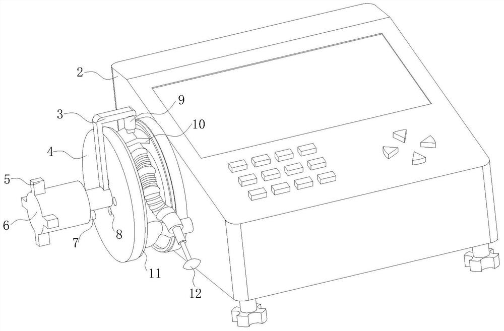
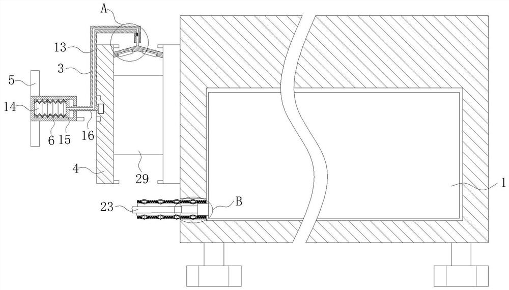
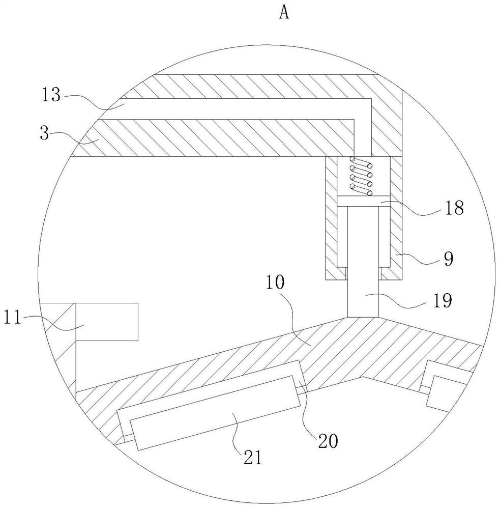
[0030] As an embodiment of the present invention, the bottom of the wire management rod 10 is provided with a mounting groove 20; the inside of the installation groove 20 is provided with a rubber roller 21; when the wire management rod 10 rotates, the rubber roller 21 moves from The surface of the optical fiber sleeve 28 rolls over; during work, the rubber roller 21 converts the sliding friction between the wire management rod 10 and the optical fiber sleeve 28 into rolling friction between the rubber roller 21 and the optical fiber sleeve 28, thereby greatly reducing The friction resistance between the optical fiber sleeve 28 and the surface of the cable management rod 10 is reduced, so that the movement of the cable management rod 10 is more convenient and the optical fiber sleeve 28 is embedded between the two sets of limiting discs 4 for storage.

[0031] As an embodiment of the present invention, the optical fiber sleeve 28 is evenly provided with a rubber airbag ring 31;...


PUM


Abstract

The invention belongs to the technical field of spectrometers for clinical use, and specifically relates to a connection and storage device for an optical fiber and a spectrometer for clinical use, including a spectrometer body; a host shell is arranged outside the spectrometer body; the spectrometer body is detachably connected through a flange There is an optical fiber; the optical fiber passes through the threading groove on the spectrometer body and is fixedly connected to the probe; the outside of the optical fiber is covered with a fiber sleeve; one end of the fiber sleeve is fixedly connected to the inside of the threading groove, and the other end of the fiber sleeve is connected to the top of the probe Fixed connection; both the optical fiber and the optical fiber sleeve are wound on the winding reel; the optical fiber sleeve is made of rubber; the winding reel is fixedly installed on the outer wall of the main machine shell; the two ends of the winding reel are fixed with limiting discs; the invention The optical fiber in the optical fiber is detachably connected through the flange, while the optical fiber sleeve is directly connected to the host shell, and the optical fiber and the optical fiber sleeve are installed separately, so that the size of the optical fiber sleeve can not be limited by the size of the optical fiber and the flange .

Description

technical field [0001] The invention belongs to the technical field of spectrometers for clinical use, and specifically relates to a connection and storage device for optical fibers and spectrometers for clinical use. Background technique [0002] The spectrometer is a basic equipment for observing, analyzing and processing the structure and composition of substances by applying optical principles. It has the advantages of high analysis precision, large measurement range, fast speed and less sample consumption. Therefore, it is widely used in metallurgy, geology, petrochemical, medical and health, environmental protection and other departments, and is also an indispensable instrument for military reconnaissance, space exploration, resource and hydrological survey. [0003] Spectroscopic technology can be used to detect human body signals. It is necessary to attach an optical probe to the skin of the arm, abdomen, etc., and connect the probe to the spectrometer in the host wi...

Claims


Application Information

Patent Timeline
Patent Type & Authority Patents(China)
IPC IPC(8): A61B5/00
CPCA61B5/0075
Inventor 聂荣志周淼淼彭波储涛熊泉赵子健张广维钟文婷
Owner 浙江澍源智能技术有限公司
Learn More