Cutting tool

A technology for cutting tools and shells, applied in the field of electric circular saws, can solve the problems of low motor efficiency and no consideration of circuit board heat dissipation, and achieve good heat dissipation and high cutting efficiency

Pending Publication Date: 2021-06-08
POSITEC POWER TOOLS (SUZHOU) CO LTD
View PDF0 Cites 2 Cited by
  • Summary
  • Abstract
  • Description
  • Claims
  • Application Information

AI Technical Summary

Problems solved by technology

[0003] At present, the electric circular saws using the above-mentioned layout often use brushed motors, and the motor efficiency is low; and the heat dissipation of the circuit board is not considered.

Method used


Image

  • Cutting tool
  • Cutting tool
  • Cutting tool

Examples


Embodiment Construction

[0045] Exemplary embodiments of the present invention are described below with reference to the accompanying drawings. It should be understood that these specific descriptions are only used to teach those skilled in the art how to implement the present invention, but are not intended to exhaust all possible ways of the present invention, nor are they intended to limit the scope of the present invention.

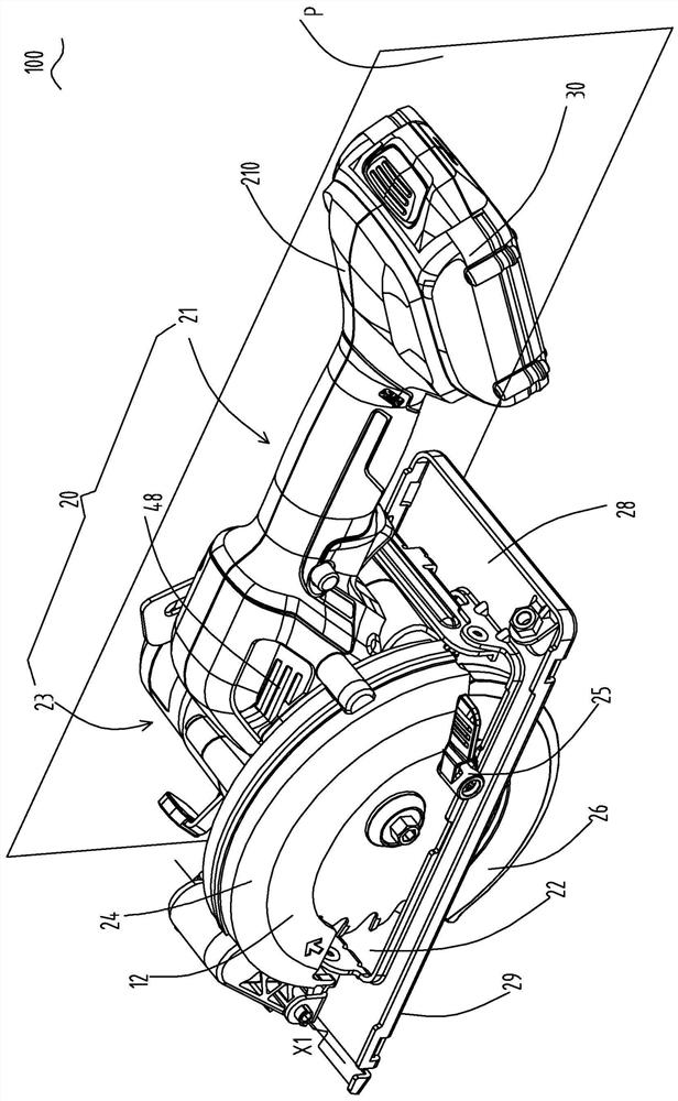
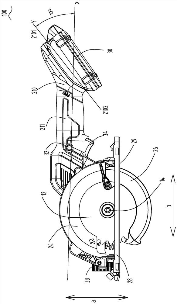
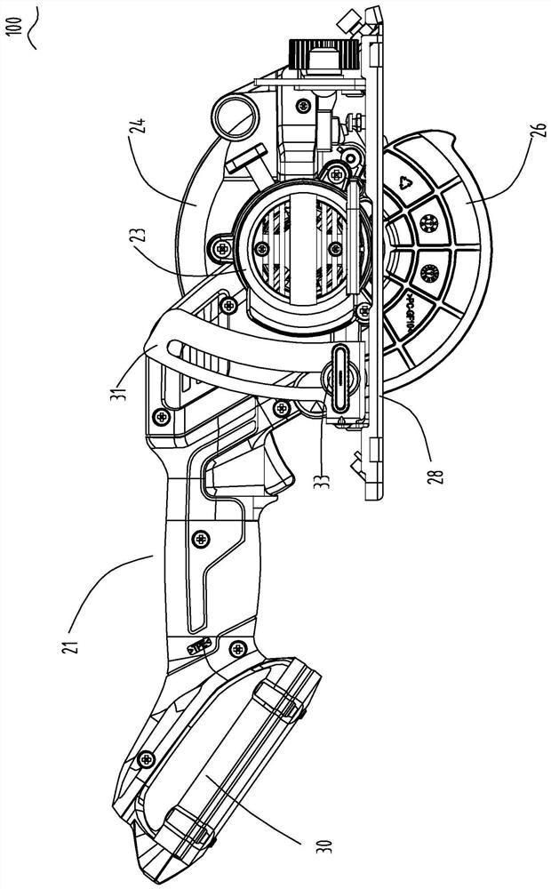
[0046] Such as Figure 1 to Figure 12 As shown, the first embodiment of the present invention provides a cutting tool 100, especially an electric circular saw, comprising: an output shaft 14 for installing a saw blade 12; a motor for driving the output shaft 14 to rotate, and the motor has a motor Shaft; the transmission device arranged between the output shaft 14 and the motor shaft is used to transmit the motion of the motor to the output shaft 14; the housing 20 is used to accommodate parts such as the motor and the transmission device; the shield assembly is attached to t...


PUM


Abstract

The invention provides a cutting tool. The cutting tool comprises an output shaft, a brushless motor, a fan and a shell, wherein the brushless motor is provided with a motor shaft; the fan is supported by the motor shaft and is used for generating cooling airflow; the shell comprises a first shell and a second shell; the first shell is provided with a handle portion for a user to grab and is provided with a first end connected with the second shell and a second end connected with a power supply device; the second shell is used for accommodating the motor and a transmission device; the cutting tool further comprises a circuit board; the circuit board is accommodated in the first shell; cooling air holes are further formed in the shell; and when the fan rotates, the circuit board and the motor are both arranged in a channel of the cooling airflow. Compared with the prior art, the cutting tool provided by the invention has the advantage that the circuit board and the cooling air holes are reasonably arranged, so that heat dissipation can be effectively carried out on the circuit board and the motor.

Description

technical field [0001] The invention relates to a cutting tool, especially an electric circular saw. Background technique [0002] In recent years, new layouts for portable electric circular saws have been investigated for size and efficiency. The layout includes the following structure: the housing of the host computer includes a first housing and a second housing; the first housing extends along the lengthwise direction and includes a first end for connecting to the second housing and a first end for connecting to a power supply device The second end and the middle part of the first housing are configured as handles for users to grasp; the second housing accommodates the motor and the transmission device. Different from the traditional electric circular saw that arranges the motor in the handle, on the one hand, this layout can not be limited by the size of the motor, and the radial size of the handle can be designed within a reasonable range, which is convenient to hold;...

Claims


Application Information

Patent Timeline
IPC IPC(8): B23D45/16B25F5/00
CPCB23D45/16B25F5/008B25F5/00B27G19/04B27B9/02B23D47/12
Inventor 毋宏兵吉绍山马一纯孟瑞马建英
Owner POSITEC POWER TOOLS (SUZHOU) CO LTD
Why Eureka
Try Eureka