Laser welding method for aircraft engine exhaust pipe end flange

An aircraft engine, laser welding technology, applied in laser welding equipment, welding equipment, tubular objects, etc., can solve the problems of poor service reliability and low exhaust pipe accuracy, achieve convenient assembly, reduce welding deformation, and reliable butt welding Effect

Pending Publication Date: 2021-06-08
AVIC BEIJING AERONAUTICAL MFG TECH RES INST
View PDF7 Cites 2 Cited by
  • Summary
  • Abstract
  • Description
  • Claims
  • Application Information

AI Technical Summary

Problems solved by technology

[0008] The embodiment of the present invention provides a laser welding method for the flange of the exhaust pipe end of an aircraft engine. By designing the flange, the shape of the welding edge of the cylinder and the planning of the laser welding path, it can not only overcome the problems of machined flanges and sheet metal cylinders. The conventional butt joint assembly accuracy cannot meet the limitations of laser welding requirements, which makes the flange and cylinder assembly convenient, and can use the strong penetration of laser welding to completely melt the connection interface between the flange and the cylinder to achieve reliable docking of the two Welding, which solves the technical problems of low precision and poor service reliability when argon arc welding exhaust pipes

Method used


Image

  • Laser welding method for aircraft engine exhaust pipe end flange
  • Laser welding method for aircraft engine exhaust pipe end flange
  • Laser welding method for aircraft engine exhaust pipe end flange

Examples


Embodiment 1

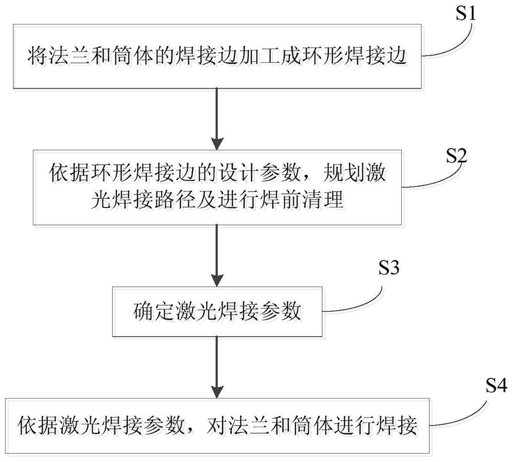
[0084] An aircraft engine exhaust pipe is made of 0Cr18Ni9 stainless steel, the initial welding edge of the flange is 5mm, and the welding edge of the cylinder is 1mm. The technical solution of the present invention is used to realize the laser welding of the end flange, which mainly includes the following steps:

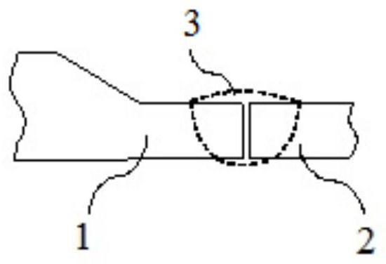
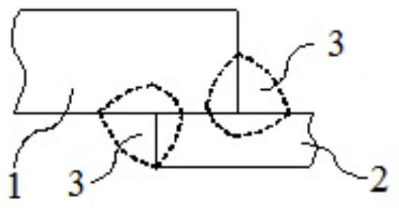
[0085] Step 1: Process flange 1 and cylinder 2 annular welding edges. The welding edge of flange 1 is based on the inner wall of the exhaust pipe, processed to a wall thickness of δ = 3mm, the length of the δ wall thickness state is L = 5mm, and an annular groove is prepared on the inner side of the welding edge of flange 1 to match the cylinder body 2 The welded edge forms a plug-in assembly; the depth a of the annular groove is a=0.5mm, and the radial height of the annular groove is consistent with the wall thickness of the cylinder 2, that is, 1mm. After the flange 1 and the welding edge of the cylinder 2 are assembled, the inner surface between the two is basica...

Embodiment 2

[0091] An aircraft engine exhaust pipe is made of 0Cr18Ni9 stainless steel, the initial welding edge of the flange is 5mm, and the welding edge of the cylinder is 1mm. The technical solution of the present invention is used to realize the laser welding of the end flange, which mainly includes the following steps:

[0092] Step 1: Process flange 1 and cylinder 2 annular welding edges. The welding edge of flange 1 is based on the inner wall of the exhaust pipe, processed to a wall thickness of δ = 3mm, the length of the δ wall thickness state is L = 5mm, and an annular groove is prepared on the inner side of the welding edge of flange 1 to match the cylinder body 2 The welded edge forms a plug-in assembly; the depth a of the annular groove is a=0.5mm, and the radial height of the annular groove is consistent with the wall thickness of the cylinder 2, that is, 1mm. After the flange 1 and the welding edge of the cylinder 2 are assembled, the inner surface between the two is basica...


PUM

PropertyMeasurementUnit
thicknessaaaaaaaaaa
lengthaaaaaaaaaa
depthaaaaaaaaaa

Abstract

The invention relates to a laser welding method for an aircraft engine exhaust pipe end flange. The laser welding method comprises the following steps that 1, welding edges of a flange and a cylinder are machined into annular welding edges; 2, according to the design parameters of the annular welding edges, a laser welding path is planned, and pre-welding cleaning is conducted; 3, laser welding parameters are determined; and 4, the flange and the cylinder are welded according to the laser welding parameters. The laser welding method for the aircraft engine exhaust pipe end flange aims at solving the problems of low precision and poor service reliability during argon arc welding of an exhaust pipe.

Description

technical field [0001] The invention relates to the technical field of exhaust pipe manufacturing, in particular to a laser welding method for a flange at the end of an aircraft engine exhaust pipe. Background technique [0002] The engine exhaust pipe of a large-scale fire fighting / water rescue amphibious aircraft includes parts such as flanges, barrels, and reinforcing rings. The flange is usually arranged at the end of the exhaust pipe and installed near the engine through fasteners; the flange is a ring-shaped machined part, and the thickness of the part connected to the cylinder is 4mm to 8mm. The cylinder is a thin-walled shell structure, usually manufactured by sheet metal method, the central axis is a space curve, and the wall thickness ranges from 0.8mm to 1.5mm. The reinforcing ring is usually set at the tail of the exhaust pipe, and is also installed on the body through fasteners. The length of the exhaust pipe ranges from 500mm to 2000mm, and the cross-sectional...

Claims


Application Information

Patent Timeline
Patent Type & Authority Applications(China)
IPC IPC(8): B23K26/24B23K26/60
CPCB23K26/24B23K26/60B23K2101/04
Inventor 许飞陈俐马旭颐郭路云
Owner AVIC BEIJING AERONAUTICAL MFG TECH RES INST
Why Eureka
Try Eureka