
To-be-machined workpiece positioning method and to-be-machined workpiece positioning system

A technology of workpiece to be processed and positioning method, which is applied in the field of data capture and can solve the problems of limited edge-finding function and the inability of capacitive edge-finding function to locate the plate origin and offset angle.

Pending Publication Date: 2021-06-08
HANS LASER TECH IND GRP CO LTD +1
View PDF6 Cites 0 Cited by
  • Summary
  • Abstract
  • Description
  • Claims
  • Application Information

AI Technical Summary

Problems solved by technology

[0003] Based on this, it is necessary to provide a positioning method of the workpiece to be processed and an GPS

Method used


Image

  • To-be-machined workpiece positioning method and to-be-machined workpiece positioning system
  • To-be-machined workpiece positioning method and to-be-machined workpiece positioning system
  • To-be-machined workpiece positioning method and to-be-machined workpiece positioning system

Examples


Embodiment Construction

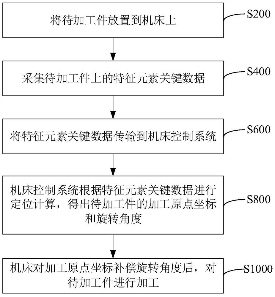
[0090] Such as figure 1 As shown, it is a schematic flow chart of the positioning method of the workpiece to be processed provided by the embodiment of the present invention, and the method specifically includes the following steps:

[0091] S200: placing the workpiece to be processed on the machine tool.

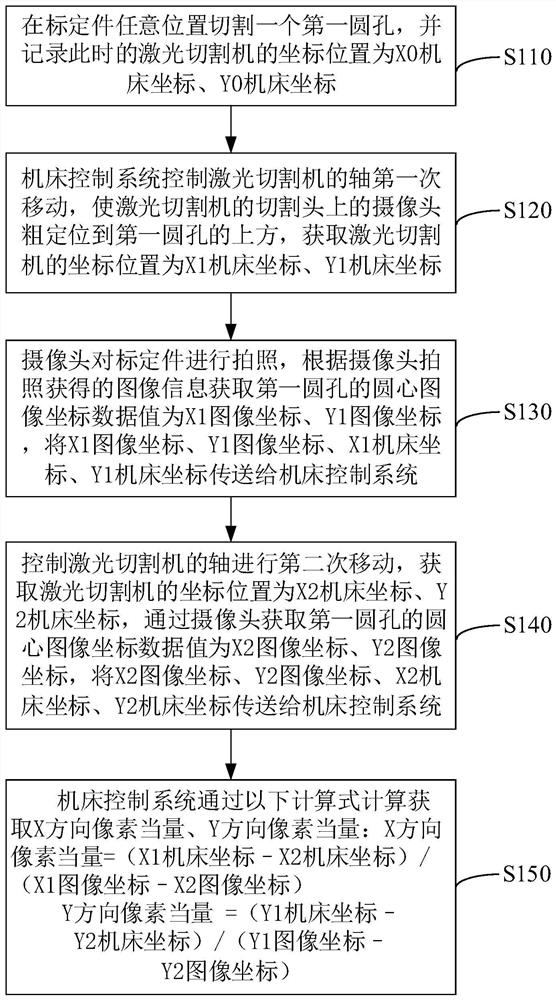
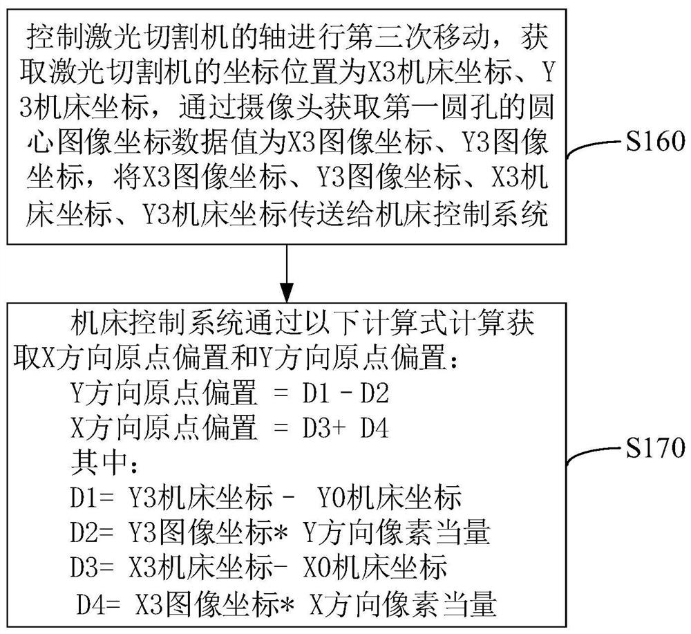
[0092] In one of the embodiments, before placing the workpiece to be processed on the machine tool, a calibration step is also included. The calibration step may specifically include obtaining the pixel equivalent in the X direction, the pixel equivalent in the Y direction, the origin offset in the X direction, and the origin offset in the Y direction. The X and Y directions are the horizontal direction of the machine tool and are perpendicular to each other.

[0093] In one of the embodiments, the above-mentioned machine tool can be a laser cutting machine, such as figure 2 As shown, it is a schematic flow chart of obtaining the pixel equivalent in the X direction and t...


PUM


Abstract

The invention relates to a to-be-machined workpiece positioning method and a to-be-machined workpiece positioning system. The method comprises the steps that a to-be-machined workpiece is placed on a machine tool; key data of feature elements on the to-be-machined workpiece are collected; the key data of the feature elements are transmitted to a machine tool control system; the machine tool control system carries out positioning calculation according to the key data of the feature elements to obtain the machining origin coordinates and the rotation angle of the to-be-machined workpiece; and after the machine tool compensates the rotation angle for the machining origin coordinates, the to-be-machined workpiece is machined. According to the to-be-machined workpiece positioning method and the to-be-machined workpiece positioning system, by collecting and transmitting the key data of the feature elements on the to-be-machined workpiece to the machine tool control system, the machining origin coordinates and the rotation angle are obtained, the to-be-machined workpiece is machined, and the problems that when a machine tool conducts plate machining, the original point and the offset angle of a plate cannot be positioned through a traditional capacitor edge searching function, and the edge searching function is limited are effectively solved.

Description

technical field [0001] The invention relates to the technical field of data capture, in particular to a positioning method for a workpiece to be processed and a positioning system for the workpiece to be processed. Background technique [0002] For machine tools such as fiber laser cutting machines and other fields, in the processing process, the plate that has been processed once by other CNC machine tools needs to be processed twice by the fiber laser cutting machine. The traditional capacitor edge-seeking function cannot locate the origin and offset of the plate. If the angle is set, the edge finding function is limited. Contents of the invention [0003] Based on this, it is necessary to provide a positioning method of the workpiece to be processed and an GPS. [0004] A method for positioning a workpiece to be processed, comprising: [0005] Place the workpiece to be processed on the machine tool; [0006] Collect key data of characteristic elements on the workpie...

Claims


Application Information

Patent Timeline
IPC IPC(8): B23K26/38B23K26/70
CPCB23K26/38B23K26/702Y02P90/02
Inventor 杨志朋胡三锋赵春平陈焱蔡建平何纯贤高云峰
Owner HANS LASER TECH IND GRP CO LTD
Learn More