Automatic cutter passivation device

A technology for moving tools and cutting tools, applied in the direction of manufacturing tools, grinding feed motion, other manufacturing equipment/tools, etc., can solve the problems of low degree of automation, low passivation efficiency, and substandard passivation accuracy

Pending Publication Date: 2021-06-08
HARBIN UNIV OF SCI & TECH
View PDF7 Cites 2 Cited by
  • Summary
  • Abstract
  • Description
  • Claims
  • Application Information

AI Technical Summary

Problems solved by technology

[0003] The purpose of the present invention is to provide an automatic passivation tool device to solve the problems of low p

Method used


Image

  • Automatic cutter passivation device
  • Automatic cutter passivation device
  • Automatic cutter passivation device

Examples


Embodiment Construction

[0016] specific implementation plan

[0017] The present invention will be described in further detail below in conjunction with the accompanying drawings.

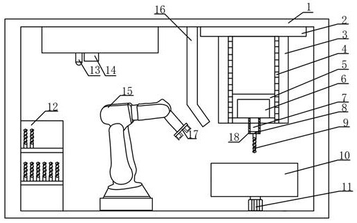
[0018] Such as figure 1 As shown, an automatic passivation tool device includes a frame 1, a turntable 2 is installed on the frame 1, and a linkage table 3 is fixed with the turntable 2. The linkage table 3 is in the shape of a regular tetrahedron, and the vertical direction A first motor 6 and two guide rails 4 are respectively installed on the four faces, and the lifting table 5 can move vertically along the guide rails 4. The first motor 6 is installed on the lifting table 5 and can rotate at a certain angle. The transmission shaft 7 One end is connected with the first motor 6, and the other end is equipped with a tool clamping device 8, which clamps the tool 9. When the tool 9 rotates with the turntable 2, it is also driven by the first motor 6 to rotate itself.

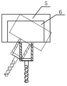
[0019] Such as figure 1 and image 3 As shown, the...


PUM


Abstract

The invention relates to an automatic cutter passivation device, and belongs to the technical field of cutter surface machining. The automatic cutter passivation device is divided into a passivation area, a detection area and a feeding and discharging area. The passivation area comprises a rotating disc, a linkage table, a guide rail, a lifting table, a first motor, a second motor, a transmission shaft, a cutter clamping device, a transmission shaft protection sleeve, a grinding material barrel, a first blast pipe and the like. The detection area comprises a photoelectric sensor, a scanning electron microscope lens and the like. The feeding and discharging area comprises a mechanical arm, a mechanical gripper, a cutter frame and the like. When the automatic cutter passivation device works, a cutter is moved to the three areas through the mechanical arm, the cutter clamping device clamps the cutter in the passivation area and inserts the cutter into the grinding material barrel to passivate the cutter, the requirement for machining different cutter cutting edges is met, the shape of the cutter cutting edges is detected in the detection area, and the cutter is assembled and disassembled in the feeding and discharging area. The automatic cutter passivation device is easy to operate, high in passivation efficiency and high in automation degree, and the passivation precision meets the machining and production requirements.

Description

technical field [0001] The invention relates to an automatic passivation tool device, which belongs to the technical field of tool surface processing. Background technique [0002] With the development of science and technology and the introduction of the old and the new in the machinery industry, various parts with different structures, materials, complexity and shapes are constantly appearing, and the processing of these parts has certain requirements for the tool. During the cutting process of the tool, the blade itself is subjected to high temperature, high pressure, wear and vibration, resulting in frequent wear and chipping of the tool, which affects the life of the tool, processing cost and production efficiency. The most commonly used method in industrial production is to align the blade. The ground tool is passivated to eliminate burrs and gaps on the cutting edge surface, thereby increasing the service life of the tool, improving processing efficiency and reducing ...

Claims


Application Information

Patent Timeline
IPC IPC(8): B24B3/00B24B31/02B24B31/12B24B41/06B24B41/00B24B49/12B24B49/10
CPCB24B3/00B24B31/003B24B31/02B24B31/12B24B41/06B24B41/005B24B49/12B24B49/10
Inventor 王义文李鹏飞苗宇航付鹏强张广钿王昭姜晓灿
Owner HARBIN UNIV OF SCI & TECH
Why Eureka
Try Eureka