Device for polishing welding seam inside pressure vessel

A pressure vessel, internal welding technology, applied in grinding/polishing safety devices, grinding machines, grinding racks, etc., can solve the problems of environmental protection, low grinding efficiency and unsafety

Inactive Publication Date: 2021-06-08
湛立宁
View PDF8 Cites 5 Cited by
  • Summary
  • Abstract
  • Description
  • Claims
  • Application Information

AI Technical Summary

Problems solved by technology

[0003] The invention provides a welding seam grinding device inside a pressure vessel, which is used to solve the technical problem that the current tra

Method used


Image

  • Device for polishing welding seam inside pressure vessel
  • Device for polishing welding seam inside pressure vessel
  • Device for polishing welding seam inside pressure vessel

Examples


Embodiment 1

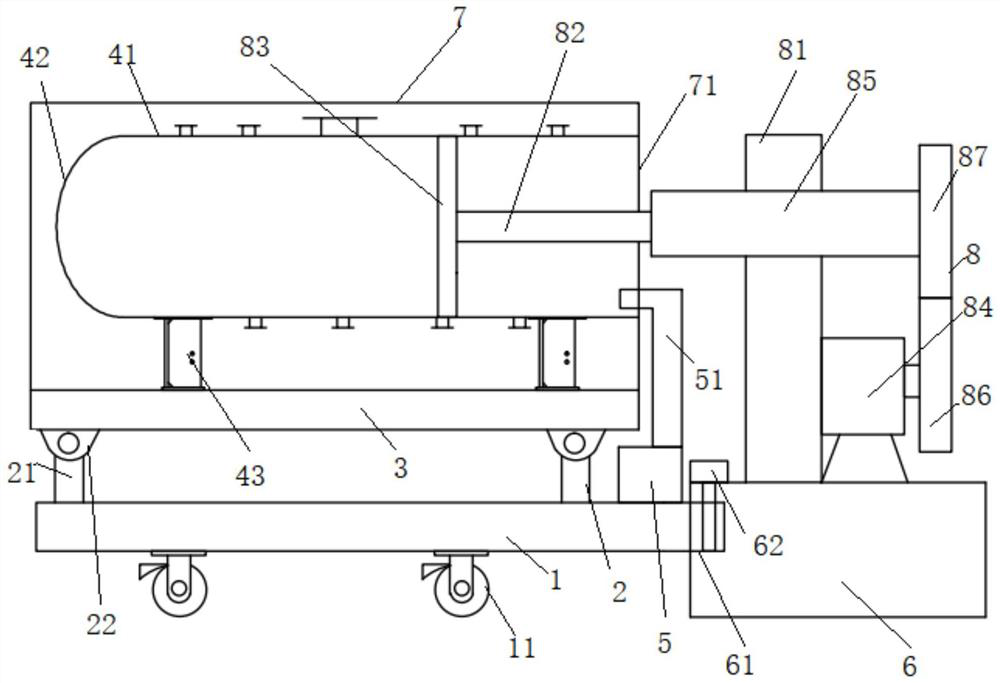
[0066] The embodiment of the present invention discloses a pressure vessel internal weld seam grinding device 8, such as figure 1 shown, including:

[0067] A moving seat 1, a plurality of moving wheels 11 are arranged at the lower end of the moving seat 1;

[0068] The first angle adjustment device 2 is installed on the upper end of the moving seat 1;

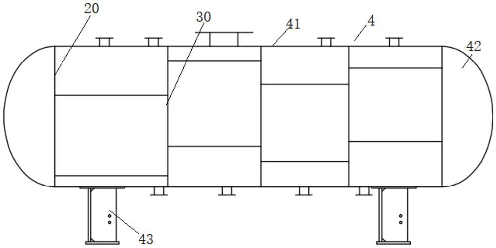
[0069] Mounting seat 3, the lower end is installed on the working end of the upper end of the first angle adjustment device 2, the upper end of the mounting seat 3 is installed with the pressure vessel 4 to be polished, and at least one end of the pressure vessel 4 to be polished is provided with a detachable head 41. The mounting base 3 or the moving base 1 is also connected with a dust collection device 5;

[0070] The fixed seat 6 is located on one side of the mobile seat 1, and the side of the mobile seat 1 close to the fixed seat 6 is provided with a limit block 61, and the limit block 61 is used to be inserted into the...

Embodiment 2

[0089] On the basis of Example 1, such as figure 1 As shown, the first angle adjusting device 2 includes: several third telescopic rods 21, which are evenly arranged along the peripheral side of the mounting seat 3, and the lower ends of the third telescopic rods 21 are fixedly connected to the upper end of the moving seat 1, The upper end of the third telescopic rod 21 is rotatably connected to the lower end of the mounting base 3 through a hinge seat 22 . (Preferably, the hinge seat on the left side can also be fixed to the mounting seat, and the hinge seat on the right side can be slidably connected to the mounting seat)

[0090] The beneficial effect of the above technical solution is that: the above first angle adjusting device has the advantage of simple structure.

Embodiment 3

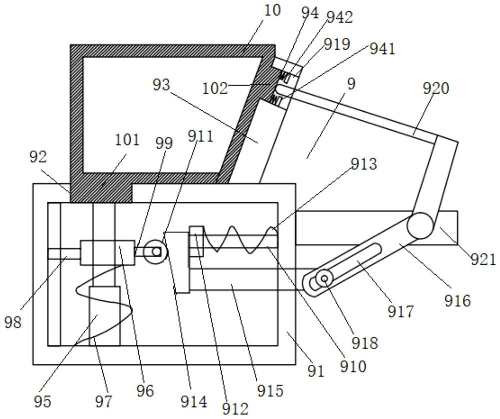
[0092] On the basis of embodiment 1 or 2, such as image 3 As shown, the dust outlet of the dust suction device 5 is also connected with a dust collection box 10, and the mounting base 3 or the moving base 1 is also connected with a mounting mechanism 9, and the mounting mechanism 9 includes:

[0093] An installation box 91, the upper end of the installation box 91 is provided with a first installation through hole 92, and the lower end of the dust collection box 10 is provided with a first positioning block 101 for inserting into the first installation through hole 92;

[0094] The fixed block 93 is fixedly connected to the upper end of the installation box 91 and is located on one side of the dust collection box 10. The upper part of the fixed block 93 is provided with a second installation through hole 919;

[0095] The second positioning block 102 is arranged on the side wall of the dust box 10, and the second positioning block 102 is used to be inserted into the second in...


PUM


Abstract

The invention provides a device for polishing a welding seam inside a pressure vessel. The device comprises a moving base; a first angle adjusting device, wherein the first angle adjusting device is arranged at the upper end of the moving base; a mounting base, wherein the mounting base is arranged at the working end of the upper end of the first angle adjusting device, the to-be-polished pressure vessel is mounted at the upper end of the mounting base, and a dust suction device is further connected to the mounting base or the moving base. a fixed base, wherein the fixed base is located on one side of the moving base, and the moving base is provided with a limiting block used for being inserted into a limiting groove in the fixed base and locked through a locking piece; a sealing cover, wherein the sealing cover is detachably connected to the upper end of the mounting base, a first opening is formed in the side, close to a sealing head, of the sealing cover, a sealing door capable of being opened or closed is connected to the first opening, and a dust suction pipe of the dust suction device is connected to the sealing cover; and a polishing device, wherein the polishing device is installed at the upper end of the fixed base, and the polishing end of the polishing device extends into the pressure vessel to be polished from the first opening. By arranging the automatic polishing device, automatic polishing is achieved, workers are prevented from entering the vessel for polishing, and the device is safe, environmentally friendly and high in polishing efficiency.

Description

technical field [0001] The invention relates to the technical field of grinding, in particular to a welding seam grinding device inside a pressure vessel. Background technique [0002] According to the "Special Equipment Safety Law of the People's Republic of China" and the special equipment safety technical specification "Stationary Pressure Vessel Safety Technical Supervision Regulations", in-use pressure vessels must undergo regular inspections to determine whether the inspected pressure vessels can operate safely to the next level. a test cycle. The most important item in the inspection is the non-destructive testing of buried defects and surface defects of the weld. Ultrasonic flaw detection and magnetic particle flaw detection are usually used to detect within the range of 100mm along both sides of the weld inside the container. However, before the inspection, both sides of the weld must be polished to remove rust and reveal the metallic luster before the inspection c...

Claims


Application Information

Patent Timeline
IPC IPC(8): B24B9/04B24B49/16B24B49/00B24B55/06B24B41/02B24B41/06
CPCB24B9/04B24B41/02B24B41/067B24B49/00B24B49/16B24B55/06
Inventor 秦嗣钊湛立宁陈敏
Owner 湛立宁
Why Eureka
Try Eureka