Check patentability & draft patents in minutes with Patsnap Eureka AI!

Direct-current charging pile control guide circuit based on linear optocoupler

A DC charging pile, linear optocoupler technology, applied in the direction of logic circuits using optoelectronic equipment, battery circuit devices, logic circuits using specific components, etc., can solve the problem of poor detection accuracy, poor anti-interference ability, and inability to achieve linearization, etc. problems, to achieve the effect of improving anti-interference ability, strong reliability and improving product stability

Pending Publication Date: 2021-06-08
深圳市润诚达电力科技有限公司
View PDF7 Cites 0 Cited by
  • Summary
  • Abstract
  • Description
  • Claims
  • Application Information

AI Technical Summary

Problems solved by technology

[0003] At present, the control guidance of new energy electric vehicle charging piles on the market has poor anti-interference ability and poor detection accuracy, does not meet the new international standards, and cannot achieve linearization. When there is an error in CC, it cannot be identified, which may lead to failure to guide, and needs to be improved.

Method used


Image

  • Direct-current charging pile control guide circuit based on linear optocoupler
  • Direct-current charging pile control guide circuit based on linear optocoupler

Examples


Embodiment 1

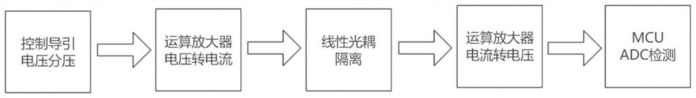
[0019] Example 1: See figure 1 , a DC charging pile control pilot circuit based on a linear optocoupler, a control pilot voltage divider module for pilot voltage division, an operational amplifier voltage-to-current module for converting voltage into a current signal, and an isolated input The output linear optocoupler isolation module is used to convert the current signal into the operational amplifier current-to-voltage module of the voltage signal, and is used for MCU ADC detection of single-chip analog-to-digital conversion. The control guide voltage divider module is connected to the operational amplifier voltage conversion module. The current module and the operational amplifier voltage-to-current module are connected to the linear optocoupler isolation module, the linear optocoupler isolation module is connected to the operational amplifier current-to-voltage module, and the operational amplifier current-to-voltage module is connected to the MCU ADC detection module.

...

Embodiment 2

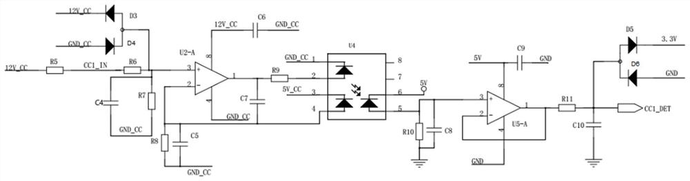
[0023] Embodiment 2. On the basis of Embodiment 1, the model of linear optocoupler U4 is HCNR201. The isolation principle of linear optocoupler U4 is the same as that of ordinary optocouplers. A light receiving circuit for feedback is used for feedback. In this way, although the two light receiving circuits are nonlinear, the nonlinear characteristics of the two light receiving circuits are the same. In this way, the non-linearity of the through path can be offset by the non-linearity of the feedback path, so as to achieve the purpose of linear isolation.


PUM


Abstract

The invention discloses a direct-current charging pile control guide circuit based on a linear optocoupler, wherein the circuit comprises a control guide voltage dividing module, an operational amplifier voltage-to-current module, a linear optocoupler isolation module, an operational amplifier current-to-voltage module, and an MCUADC detection module; the control guide voltage dividing module is connected with the operational amplifier voltage-to-current module, the operational amplifier voltage-to-current module is connected with the linear optocoupler isolation module, the linear optocoupler isolation module is connected with the operational amplifier current-to-voltage module, and the operational amplifier current-to-voltage module is connected with the MCU ADC detection module. Compared to prior art, the circuit has the beneficial effects that linearization is controlled and guided, and sampling and control are isolated; dependability is high, the MCU is isolated from the ground, and the anti-interference capability is improved; and the linearization is realized, the voltage jump of the guide loop can be measured in real time, and the product stability is improved.

Description

technical field [0001] The invention relates to the field of charging pile charging, in particular to a DC charging pile control and guiding circuit based on a linear optocoupler. Background technique [0002] The growth and rapid expansion of the new energy vehicle industry is always accompanied by the development of the charging pile industry, which is inseparable from it. In 2018, the new energy vehicle market hit a record high with sales of 1.256 million vehicles. In the first half of 2019, 617,000 vehicles have been sold, with pure electric vehicles accounting for about 80%. It is predicted that the sales of new energy vehicles in China will reach 1.6 million. In the context of the decline in overall automobile sales, the market performance of new energy vehicles is still eye-catching, and the decline in subsidies has also contributed to the strengthening of the competitiveness of the new energy vehicle market. The increase in the number of new energy vehicles is the...

Claims


Application Information

Patent Timeline
IPC IPC(8): B60L53/31B60L53/60H02J7/00H03K19/14
CPCB60L53/60B60L53/31H02J7/00H03K19/14Y02T10/70Y02T10/7072Y02T90/12
Inventor 张宏坤黄庭山
Owner 深圳市润诚达电力科技有限公司
Features
  • R&D
  • Intellectual Property
  • Life Sciences
  • Materials
  • Tech Scout
  • Unparalleled Data Quality
  • Higher Quality Content
  • 60% Fewer Hallucinations
Learn More