Continuous tray separation device, equipment and method

A separation device and separation equipment technology, used in storage devices, transportation and packaging, destacking of objects, etc., can solve problems such as low efficiency, difficult separation, and inability to achieve full automation.

Pending Publication Date: 2021-06-08
CHINA POST SCI & TECH
View PDF0 Cites 4 Cited by
  • Summary
  • Abstract
  • Description
  • Claims
  • Application Information

AI Technical Summary

Problems solved by technology

At present, there are very few nested tray separation equipments on the market. There is only a separation equipment that uses four outer surfaces to surround the spiral blades. The four-column mechanism is complex and difficult to synchronize. When it is too tight, it is not easy to separate, and it is easy to cause the failure of pallet separation; the equipment can only be replaced manually, and it cannot be fully automated, and the efficiency is low

Method used


Image

  • Continuous tray separation device, equipment and method
  • Continuous tray separation device, equipment and method
  • Continuous tray separation device, equipment and method

Examples


Embodiment 1

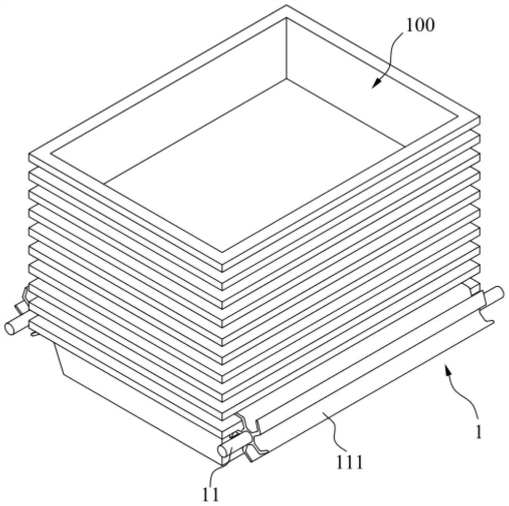
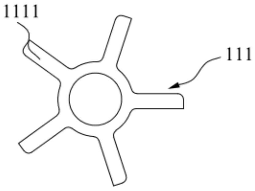
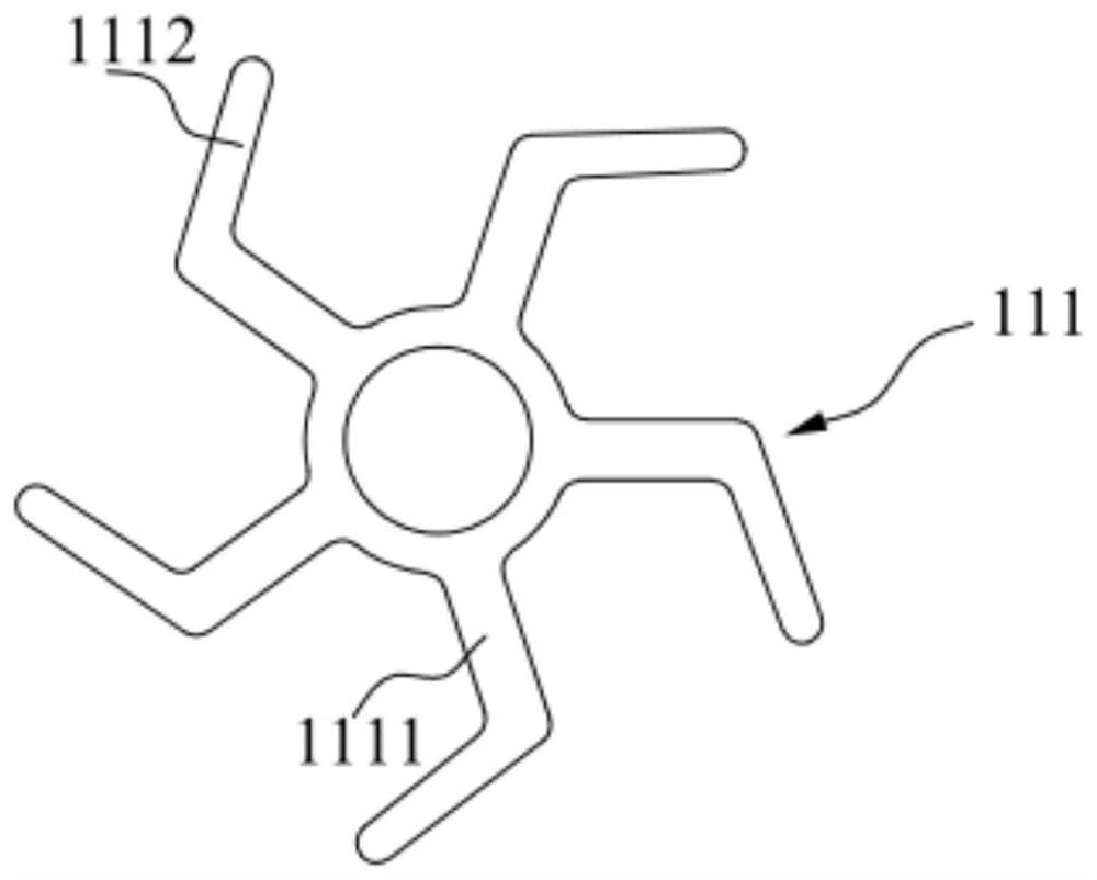
[0039] Such as Figure 1-Figure 9 As shown, the present invention provides a continuous separation device for trays, including a separation mechanism 1 and a control module. The separation mechanism 1 includes two separation rollers 11 rotatably mounted on the frame, and the two separation rollers 11 are symmetrically arranged on both sides of the tray 100. On the other hand, the outer periphery of the separating roller 11 is provided with a plurality of separating assemblies 111 extending axially along the separating roller 11, and the plurality of separating assemblies 111 are evenly distributed along the outer periphery of the separating roller 11; the control module can control the two separating rollers 11 in the axial direction The center rotates in reverse synchronously. In this embodiment, five sets of separation assemblies 111 are evenly distributed on the outer circumference of the separation rollers 11, and the control module controls the separation rollers 11 on bo...

Embodiment 2

[0049] Disclosed in this embodiment is a method for continuous separation of pallets, such as Figure 8 and Figure 9 As shown, the above-mentioned pallet continuous separation equipment is used, comprising the following steps:

[0050] S1: The propulsion device is activated, pushing the stack of trays onto the separation assembly 111 of the two separation rollers 11;

[0051] In this step, the control module controls the propulsion device to push the stacked trays onto the two separation rollers 11 , so that the bottommost tray 100 rests on the separation assemblies 111 on both sides.

[0052] S2: The tray continuous separation device starts, the two separation rollers 11 rotate in reverse synchronously, and the separation component 111 separates the bottom tray 100;

[0053] In this step, when the stack of trays in S1 is put away, the control module controls the separation rollers 11 on both sides of the tray 100 (or the separation roller 11 on one side) to rotate, and the...


PUM


Abstract

The invention belongs to the technical field of logistics warehouse distribution automation equipment, and discloses a continuous tray separation device, equipment and method. The continuous tray separation device comprises a separation mechanism and a control module, the separation mechanism comprises two separation rollers rotationally installed on a rack, and the two separation rollers are symmetrically arranged at the two sides of trays; and a plurality of separation assemblies extending in the axial direction of the separation rollers are arranged at the periphery of the separation rollers and evenly distributed along the periphery of the separation rollers. The control module can control the two separation rollers to synchronously and reversely rotate with the axial direction as the center. The continuous tray separation equipment comprises a propelling device and the continuous tray separation device, the propelling device is used for pushing a tray pile onto the two separation rollers, and the control module can control starting and stopping of the propelling device. The continuous tray separation device can achieve continuous separation of the trays, and is high in separation efficiency, simple in overall structure and low in manufacturing cost. The continuous tray separation equipment can automatically replace a tray pile, the working efficiency is improved, and full automation of the equipment is achieved.

Description

technical field [0001] The invention relates to the technical field of logistics warehouse distribution automation equipment, in particular to a pallet continuous separation device, equipment and method. Background technique [0002] With the blowout development of logistics and transportation, there are more and more special-shaped mails. The common method of storing and transporting special-shaped mails is to place them in pallet containers. Pallets are stored in stacks to save storage space. At present, there are very few nested tray separation equipments on the market. There is only one separation equipment that uses four outer surfaces to surround the spiral blades. The four-column mechanism is complicated and the synchronization is difficult. When it is too tight, it is not easy to separate, and it is easy to cause the failure of pallet separation; the equipment can only replace the pallet stack manually, which cannot be fully automated and has low efficiency. Conte...

Claims


Application Information

Patent Timeline
Patent Type & Authority Applications(China)
IPC IPC(8): B65G59/10B65G1/04B65G47/82
CPCB65G1/04B65G47/82B65G59/107B65G2201/0258
Inventor 代铁山张号王志明
Owner CHINA POST SCI & TECH
Why Eureka
Try Eureka