

Automatic capacitor assembling device
A technology for capacitor banks and driving components, applied in capacitors, capacitor manufacturing, electrolytic capacitors, etc., can solve the problems affecting the rapid production and manufacturing of capacitors, the complex structure of the cam rocker arm mechanism, and the bending and damage of the element pins, so as to achieve rapid production. The effect of high precision in manufacturing, structural operation and rapid assembly
- Summary
- Abstract
- Description
- Claims
- Application Information
AI Technical Summary
Problems solved by technology
Method used
Image

Examples
Embodiment Construction
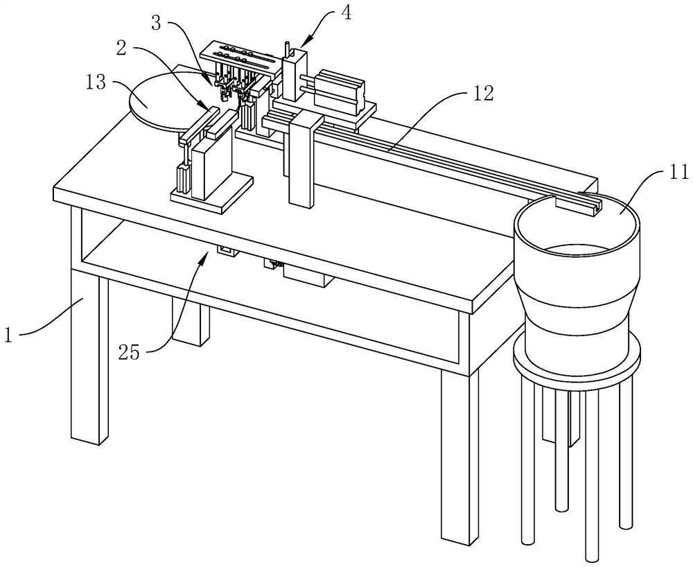
[0039] The following is attached Figure 1-7 The application is described in further detail.
[0040] The embodiment of the present application discloses an automatic capacitor assembly device. refer to figure 1 , the assembly device includes a frame 1, and the frame 1 is successively provided with a vibrating plate 11, a conveying track 12, a clamping device 2, a batch feeding device 3 and a station plate 13 along the conveying direction of the element, and the element vibrating plate The discharge end of 11 is connected with the element conveying track 12, and the clamping device 2 is arranged between the element conveying track 12 and the station disk 13, and the clamping device 2 is used for inserting the element into the colloidal particles in the station disk 13, The batch feeding device 3 is arranged on the frame 1 above the element conveying track 12 , and the batch feeding device 3 is used to clamp the element from the element conveying track 12 to the clamping end ...
PUM
 Abstract
Description
Claims
Application Information