Check patentability & draft patents in minutes with Patsnap Eureka AI!

Flight capacitance balancing circuit and method for three-level step-down DC-DC converter

A DC-DC and capacitor balancing technology, applied in the direction of output power conversion devices, instruments, electrical components, etc., can solve the problems of unbalanced flight capacitor voltage, increased system area and power consumption, large inductor current, etc., to solve the problem of flight Capacitor voltage unbalance problem, improve system stability, strong stability effect

Pending Publication Date: 2021-06-08
NORTHWESTERN POLYTECHNICAL UNIV
View PDF11 Cites 0 Cited by
  • Summary
  • Abstract
  • Description
  • Claims
  • Application Information

AI Technical Summary

Problems solved by technology

[0002] Due to the continuous expansion of application scenarios such as lithium-ion batteries and Internet of Things products, the demand for step-down DC-DC converters is also growing rapidly, especially for step-down converters with low conversion ratios, but with such characteristics The traditional two-level buck converter usually has large parasitic capacitance and switching loss, and also produces large inductor current ripple
[0003] The normalized inductor current ripple and output voltage ripple of the three-level step-down converter can be reduced by 4 times and 8 times respectively, which is very beneficial to reduce the conduction loss and switching loss of the converter. However, the three-level conversion In actual work, the converter will be affected by factors such as switching frequency, parasitic capacitance, gate control signal, etc., which will cause the voltage of the flying capacitor to be unable to balance to the input voltage V IN half of , thus having a more significant impact on the system performance of the converter
However, the circuit design is complex, which increases the area and power consumption of the system, and the feedback loop may be easily affected by the operating conditions, which is not conducive to the normal operation of the converter.

Method used


Image

  • Flight capacitance balancing circuit and method for three-level step-down DC-DC converter
  • Flight capacitance balancing circuit and method for three-level step-down DC-DC converter
  • Flight capacitance balancing circuit and method for three-level step-down DC-DC converter

Examples


Embodiment Construction

[0024] Now in conjunction with embodiment, accompanying drawing, the present invention will be further described:

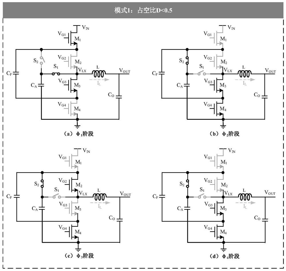
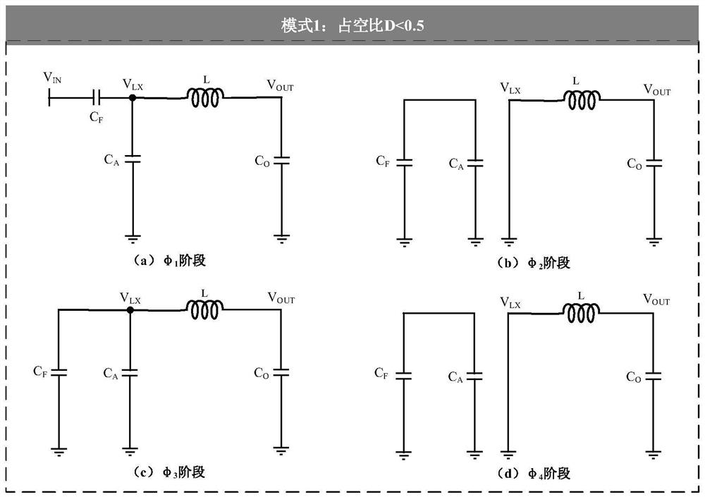
[0025] refer to Figure 1-5 , a three-level step-down DC-DC converter flight capacitor balancing circuit using auxiliary capacitors proposed by the present invention is composed of two modes, mode 1 is: when the duty cycle D0.5, the three-level step-down converter flying capacitor voltage balancing circuit.

[0026] When the duty cycle Dfigure 1 (a) shown. At this time, the circuit consists of four power tubes M 1 -M 4 , two capacitors C F 、C A and two switches S 1 , S 2 composition. Power tube M 1 The drain terminates the input signal V IN , power tube M 4 The source end of the ground is grounded, and the four power tubes M 1 -M 4 The source and drain of the switch are connected in turn; the switch S 1 with S 2 One end is connected, and the other end is respectively connected to the power tube M 2 with power tube M 3 between and the power tube M ...


PUM


Abstract

The invention relates to a three-level step-down DC-DC converter flight capacitance balancing circuit and method, and belongs to the field of power management circuits. By adding an auxiliary capacitor CA and switches S1, S2 and S3 which are equal to a flying capacitor CF in capacitance value, and by controlling the series-parallel connection mode of the flying capacitor CF and the auxiliary capacitor CA, the balance control over the voltage of the flying capacitor is achieved. According to the invention, in the two modes that the duty ratio D is smaller than 0.5 and larger than 0.5, the balance adjustment of the flight capacitor voltage of the three-level step-down converter can solve the problem that the flight capacitor voltage of the three-level buck converter is unbalanced in different duty ratio states, and the system stability is improved. Compared with a control scheme (CF-AOT) with fixed frequency and adaptive turn-on time proposed in the background technology, the structure can realize balance control of the flight capacitor voltage VCF without a complex control loop, and has the advantages of simple structure, easy adjustment and strong stability.

Description

technical field [0001] The invention belongs to the field of power management circuits, in particular to a three-level step-down DC-DC converter. Background technique [0002] Due to the continuous expansion of application scenarios such as lithium-ion batteries and Internet of Things products, the demand for step-down DC-DC converters is also growing rapidly, especially for step-down converters with low conversion ratios, but with such characteristics The traditional two-level buck converter usually has large parasitic capacitance and switching loss, and also produces large inductor current ripple. [0003] The normalized inductor current ripple and output voltage ripple of the three-level step-down converter can be reduced by 4 times and 8 times respectively, which is very beneficial to reduce the conduction loss and switching loss of the converter. However, the three-level conversion In actual work, the converter will be affected by factors such as switching frequency, p...

Claims


Application Information

Patent Timeline
Patent Type & Authority Applications(China)
IPC IPC(8): H02M3/158
CPCH02M3/158Y02B70/10
Inventor 马彦昭陈智通刘仕莹樊晓桠
Owner NORTHWESTERN POLYTECHNICAL UNIV
Features
  • R&D
  • Intellectual Property
  • Life Sciences
  • Materials
  • Tech Scout
  • Unparalleled Data Quality
  • Higher Quality Content
  • 60% Fewer Hallucinations
Learn More