
Oxygen inhalation device for long-term artificial airway patient

An artificial airway and patient technology, applied in the field of medical oxygen delivery, can solve the problems of poor oxygen humidification, dust and impurity pollution, and reduce oxygen humidity, so as to avoid excessive sputum, avoid drying and caking, and increase the contact area. big effect

Pending Publication Date: 2021-06-11
WEST CHINA FOURTH HOSPITAL OF SICHUAN UNIV
View PDF0 Cites 0 Cited by
  • Summary
  • Abstract
  • Description
  • Claims
  • Application Information

AI Technical Summary

Problems solved by technology

[0002] Critically ill patients who breathe with an artificial airway (such as a tracheotomy) will have many problems when inhaling oxygen. Common oxygen inhalation devices may cause the patient's sputum to be thick and difficult to cough up due to poor oxygen humidification effect , and the artificial airway cannot spontaneously discharge the sputum, and suffocation may occur
[0003] The traditional oxygen delivery device needs to moisten the oxygen during use, and then heat up the oxygen at the same time to avoid direct inhalation causing damage to the nasal cavity and lungs. However, the traditional oxygen delivery device only injects oxygen into sterile water during use. At the same time, the temperature of the oxygen will also reduce the humidity of the oxygen itself, which will make the patient's nasal cavity dry and agglomerated, and will generate noise during the flow of oxygen, which will reduce the recovery efficiency of the patient. During the process, external dust and impurities will enter the device and cause pollution, so an oxygen inhalation device for long-term artificial airway patients is needed

Method used


Image

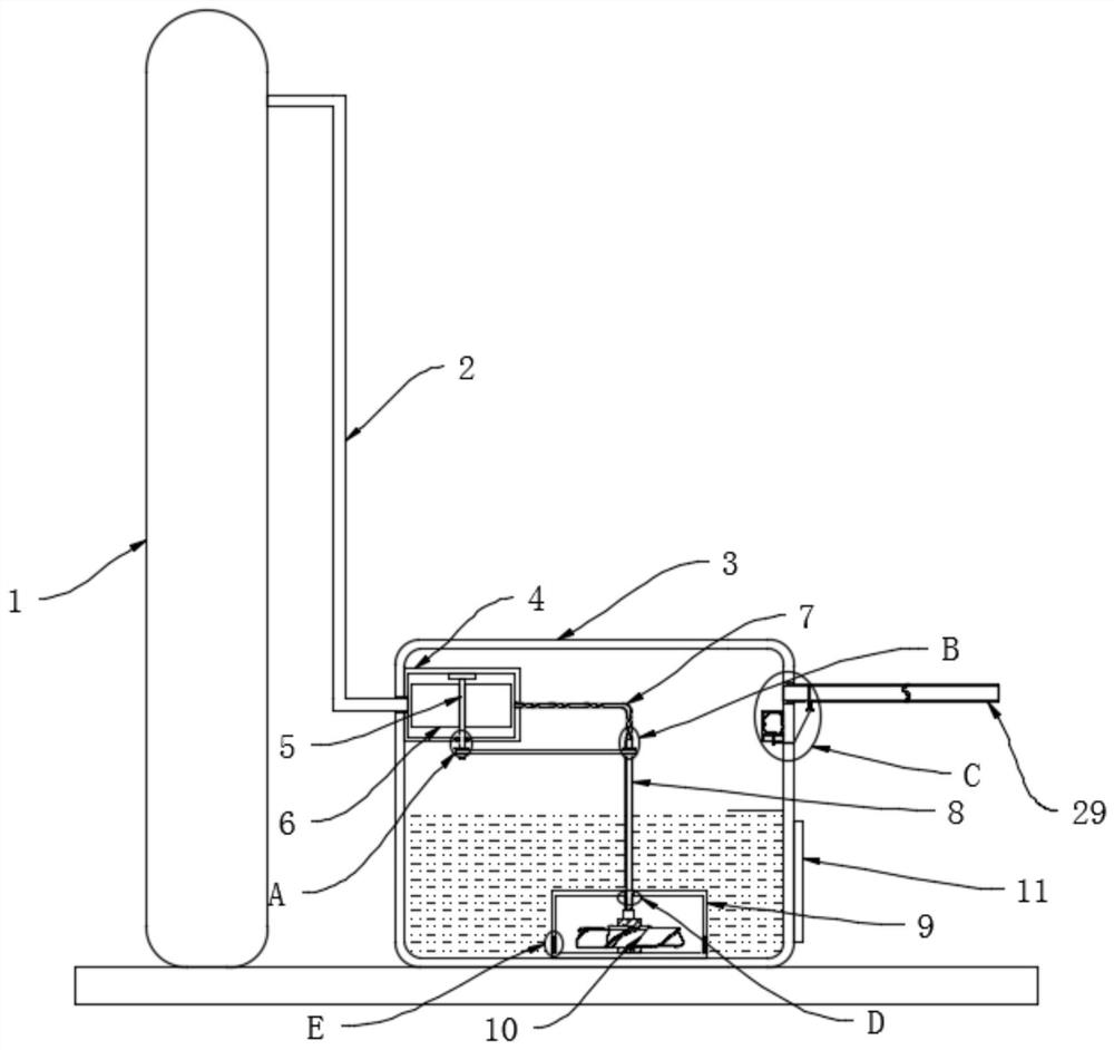
  • Oxygen inhalation device for long-term artificial airway patient
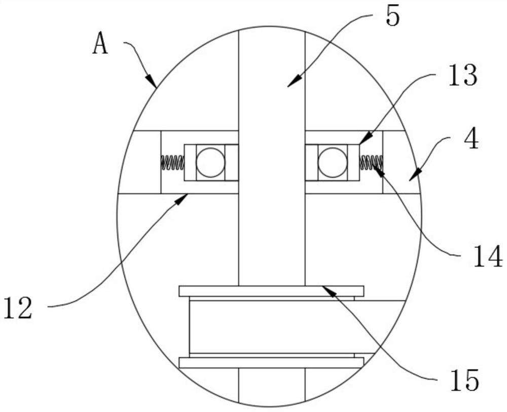
  • Oxygen inhalation device for long-term artificial airway patient
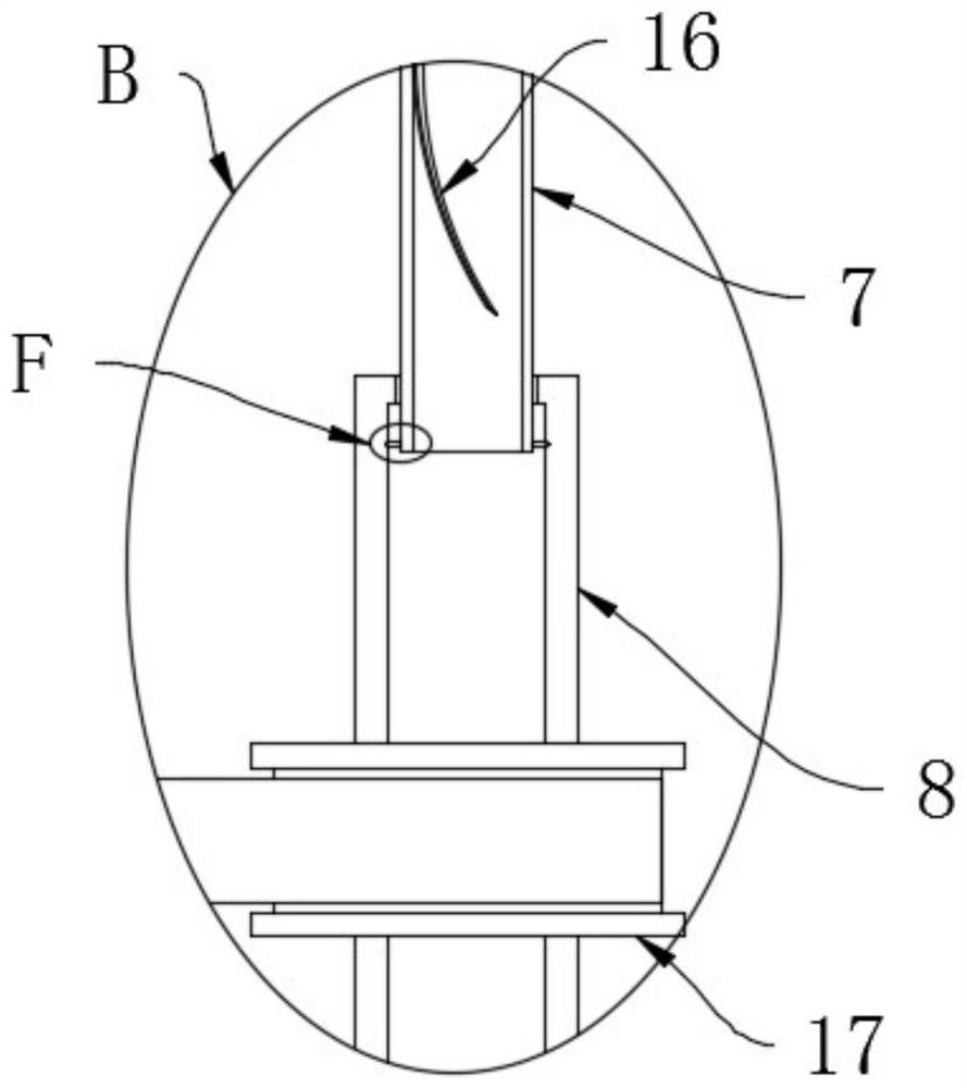
  • Oxygen inhalation device for long-term artificial airway patient

Examples


Embodiment Construction

[0026] The following will clearly and completely describe the technical solutions in the embodiments of the present invention with reference to the accompanying drawings in the embodiments of the present invention. Obviously, the described embodiments are only some, not all, embodiments of the present invention.

[0027] refer to Figure 1-8 , an oxygen inhalation device for long-term artificial airway patients, comprising an oxygen cylinder 1 and an oxygen delivery device arranged outside the oxygen cylinder 1, a drive mechanism and a humidification mechanism are arranged inside the oxygen delivery device, and the side wall of the oxygen cylinder 1 is fixed An air intake pipe 2 is connected, and the end of the air intake pipe 2 is fixedly connected with the oxygen delivery device, and the driving mechanism and the humidifying mechanism are connected by a conveyor belt;

[0028] The oxygen delivery device includes a fixed box 3, the end of the intake pipe 2 penetrates from the...


PUM


Abstract

Disclosed is an oxygen inhalation device for a long-term artificial airway patient comprising an oxygen bottle and an oxygen conveying device arranged outside the oxygen bottle, a driving mechanism and a wetting mechanism are arranged in the oxygen conveying device, an air inlet pipe is fixedly connected to the side wall of the oxygen bottle, and the tail end of the air inlet pipe is fixedly connected with the oxygen conveying device; a driving mechanism and a wetting mechanism are in transmission connection through a conveying belt, the oxygen conveying device comprises a fixing box, the tail end of the air inlet pipe penetrates into the fixing box from the exterior of the fixing box, the driving mechanism comprises a driving box fixedly connected to the interior of the fixing box, and a driving rod is movably arranged in the driving box; tiny oxygen bubbles float upwards under the action of buoyancy of the oxygen bubbles, the oxygen is moistened in the process, compared with the mode that the oxygen is directly introduced into sterile water, the contact area of the cut oxygen and the sterile water is increased, the moist purity of the patient when the patient breathes the oxygen is guaranteed, and the phenomena of dryness, caking and excessive sputum are avoided.

Description

technical field [0001] The invention relates to the technical field of medical oxygen delivery, in particular to an oxygen inhalation device for long-term artificial airway patients. Background technique [0002] Critically ill patients who breathe with an artificial airway (such as a tracheotomy) will have many problems when inhaling oxygen. Common oxygen inhalation devices may cause the patient's sputum to be thick and difficult to cough up due to poor oxygen humidification effect , and the artificial airway cannot spontaneously discharge the sputum, and suffocation may occur. [0003] The traditional oxygen delivery device needs to moisten the oxygen during use, and then heat the oxygen at the same time to avoid direct inhalation of the nasal cavity and lungs. However, the traditional oxygen delivery device only injects oxygen into sterile water and At the same time, the temperature of the oxygen will also reduce the humidity of the oxygen itself, which will make the pat...

Claims


Application Information

Patent Timeline
Patent Type & Authority Applications(China)
IPC IPC(8): A61M16/00A61M16/16
CPCA61M16/0003A61M16/16A61M2202/0208A61M2202/0007
Inventor 杜宇
Owner WEST CHINA FOURTH HOSPITAL OF SICHUAN UNIV
Learn More