
Semi-automatic machining equipment for forklift attachment mounting frame

A semi-automated, processing equipment technology, applied in the direction of metal processing equipment, metal processing machinery parts, drilling/drilling equipment, etc., can solve problems such as drill sticking, speeding up drill pipes, wear and tear, etc., so that it is not easy to break and prolongs the service life Effect

Inactive Publication Date: 2021-06-11
陈白仁
View PDF0 Cites 0 Cited by
  • Summary
  • Abstract
  • Description
  • Claims
  • Application Information

AI Technical Summary

Problems solved by technology

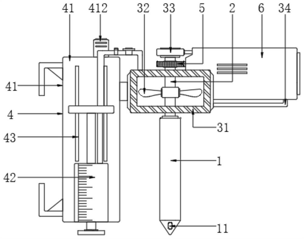
[0003] The traditional semi-automatic processing equipment for the attachment mounting frame is to directly process the rotating drill bit downwards, but the existing attachment mounting frame has a certain thickness. The waste chips generated by part of the drilling are squeezed in the hole by the drill pipe, which leads to the occurrence of drill sticking, resulting in the situation that the drill pipe cannot be rotated during the downward drilling process, and also accelerates the wear of the drill pipe Or cause the drill pipe temperature to be too high and break, thereby increasing the cost of use. For this reason, we propose a semi-automatic processing equipment for forklift attachment mounting frames

Method used


Image

  • Semi-automatic machining equipment for forklift attachment mounting frame
  • Semi-automatic machining equipment for forklift attachment mounting frame
  • Semi-automatic machining equipment for forklift attachment mounting frame

Examples


Embodiment Construction

[0021] The following will clearly and completely describe the technical solutions in the embodiments of the present invention with reference to the accompanying drawings in the embodiments of the present invention. Obviously, the described embodiments are only some, not all, embodiments of the present invention. Based on the embodiments of the present invention, all other embodiments obtained by persons of ordinary skill in the art without making creative efforts belong to the protection scope of the present invention.

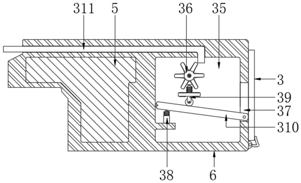
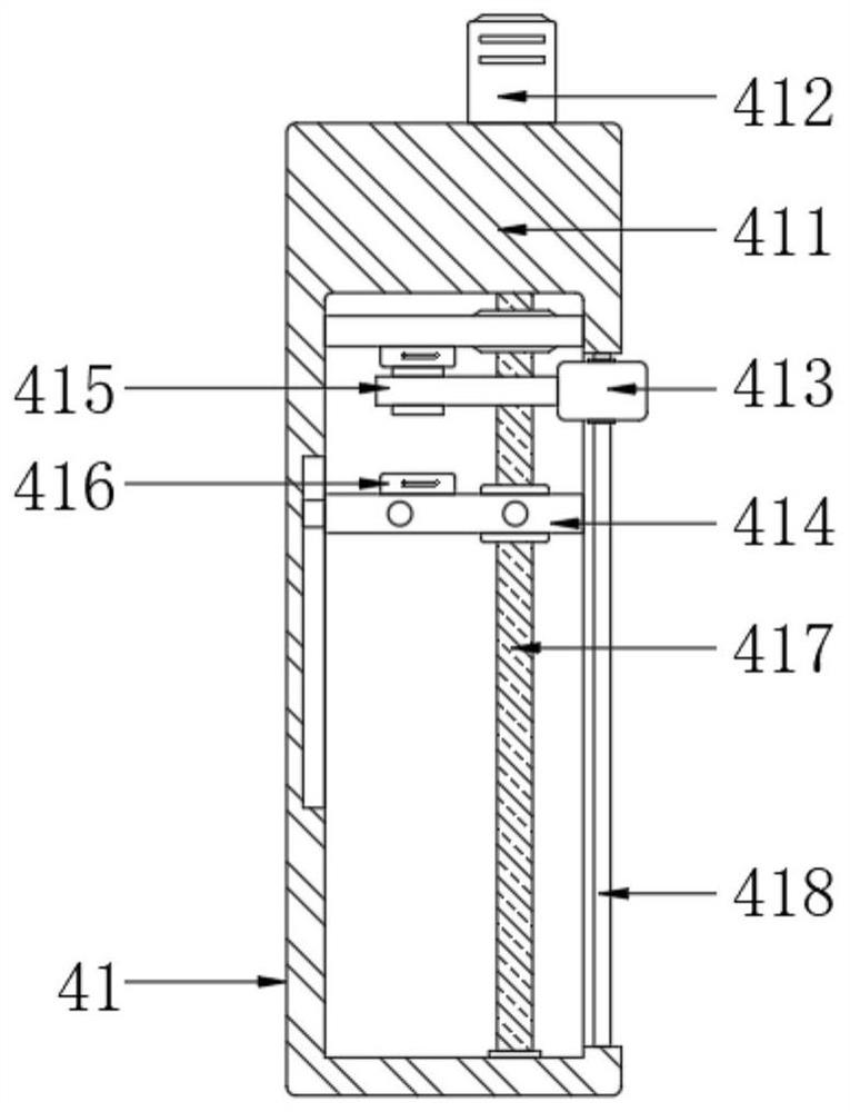
[0022] see Figure 1-4 , the present invention provides a semi-automatic processing equipment for a forklift attachment mounting frame. The electrical components in the present invention are all connected to an external power supply through wires, including a drill pipe main body 1, and a connected through rod 2 is fixed on the top of the drill pipe main body 1. , the outer wall movable sleeve of the through rod 2 is provided with an air induction assembly 3, ...


PUM


Abstract

The invention discloses semi-automatic machining equipment for a forklift attachment mounting frame, and belongs to the technical field of forklift attachment mounting frame machining. The semi-automatic machining equipment comprises a drill rod body, a through rod communicating with the drill rod body is fixed to the top of the drill rod body, the outer wall of the through rod is movably sleeved with an air inducing assembly, an intermittent assembly is fixed to the left side of the air inducing assembly, an equipment shell is fixed to the right side of the air inducing assembly, and a driving device driving the through rod to rotate is arranged on the left side of the inner part of the equipment shell. The intermittent assembly is arranged to be matched with the air inducing assembly, and by adopting the intermittent reciprocating descending mode, on one hand, a drill rod can be effectively prevented from being clamped in a hole, so that the situation that the drill rod cannot rotate is avoided; and meanwhile, the temperature of the drill rod during processing is greatly reduced, so that the drill rod is not prone to breaking, and the service life of the drill rod is prolonged.

Description

technical field [0001] The invention relates to the technical field of processing a forklift attachment mounting frame, in particular to a semi-automatic processing equipment for a forklift attachment mounting frame. Background technique [0002] In the field of heavy cargo handling, forklifts are indispensable handling tools. The forklift can lift and carry goods of different sizes, shapes and types through the attachments set at its front end. According to the use requirements of the forklift, different sizes and types of attachments can be configured on the forklift. These attachments are usually mounted on the forklift via an attachment mount located at the front of the forklift. However, due to the different types and installation methods of the attachments, installation holes need to be provided in all directions of the installation frame. The usual processing method is to cut the raw material to a fixed length, and then drill the workpiece after scribing and positi...

Claims


Application Information

Patent Timeline
Patent Type & Authority Applications(China)
IPC IPC(8): B23B41/00B23B47/20B23Q3/06B23Q11/00
CPCB23B41/00B23Q3/06B23Q5/28B23Q11/0046
Inventor 陈白仁
Owner 陈白仁
Learn More