3D printing method, supporting structure, device, equipment and storage medium

A 3D printing and supporting structure technology, applied in the field of 3D printing, can solve the problems of prolonging printing time, reducing printing speed, and multiplying printing materials, etc., to achieve the effect of increasing printing speed, reducing consumables and time-consuming, and reducing printing cost

Pending Publication Date: 2021-06-11
SHENZHEN CREALITY 3D TECH CO LTD
View PDF1 Cites 8 Cited by
  • Summary
  • Abstract
  • Description
  • Claims
  • Application Information

AI Technical Summary

Problems solved by technology

At present, when printing the support structure, after the shape of the support structure is determined, a solid solid support structure is printed directly, which not only consumes more printing materials, but also prolongs the printing time and reduces the printing speed.

Method used


Image

  • 3D printing method, supporting structure, device, equipment and storage medium
  • 3D printing method, supporting structure, device, equipment and storage medium
  • 3D printing method, supporting structure, device, equipment and storage medium

Examples


Embodiment 1

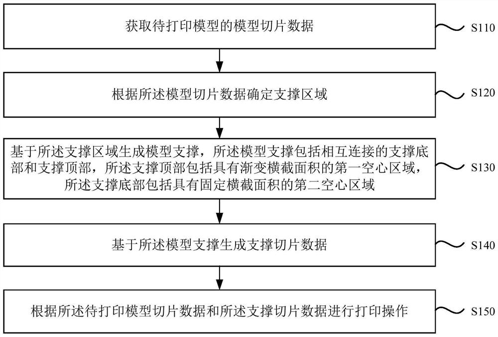
[0054] figure 1 It is a schematic flowchart of a 3D printing method provided by Embodiment 1 of the present invention. Such as figure 1 As shown, the 3D printing method provided by Embodiment 1 of the present invention includes:

[0055] S110. Obtain model slice data of the model to be printed.

[0056] Specifically, the model to be printed refers to a three-dimensional model that needs to be printed, and the model to be printed is loaded into the slicing software, and the slicing software slices it according to user requirements to generate model slicing data.

[0057] S120. Determine a support region according to the model slice data.

[0058] Specifically, the support area refers to the area where the support structure needs to be printed during the printing process. Support regions can be automatically identified by slicing software or manually set by the user. For example, in general, the model slice data actually defines the shape and printing area of ​​each slice l...

Embodiment 2

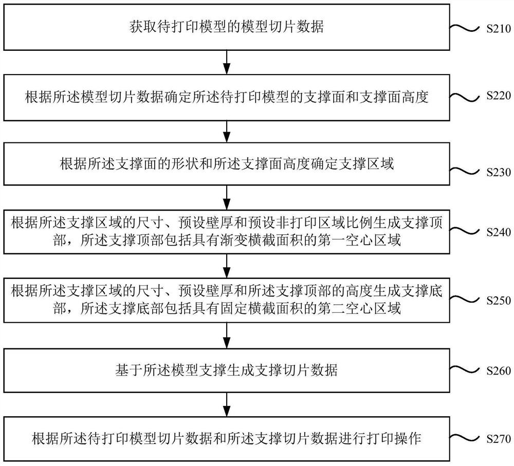
[0069] figure 2 It is a schematic flowchart of a 3D printing method provided by Embodiment 2 of the present invention. This embodiment is a further refinement of the above-mentioned embodiment. like figure 2 As shown, the 3D printing method provided by Embodiment 2 of the present invention includes:

[0070] S210. Obtain model slice data of the model to be printed.

[0071] S220. Determine the support surface and the height of the support surface of the model to be printed according to the model slice data.

[0072] Specifically, the support surface of the model to be printed is the surface of the model to be printed that needs to provide an additional support structure. The support surface can be automatically identified by the slicing software, or manually set by the user. For example, when it is detected that the printing area represented by the current slice layer data of the model is greater than the print area represented by the previous slice data and reaches the p...

Embodiment 3

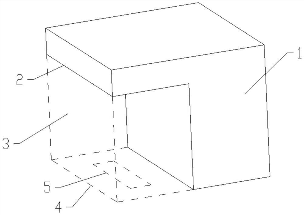
[0095] Figure 3B It is a schematic structural diagram of a 3D printing support structure provided by Embodiment 3 of the present invention. Such as Figure 3B As shown, the 3D printing support structure provided by the embodiment of the present invention includes a support bottom 10 and a support top 20 connected to each other, wherein the support top 10 includes a first hollow area 11 with a gradually changing cross-sectional area, and the support bottom 20 includes a first hollow area 11 with a fixed cross-sectional area. The cross-sectional area of ​​the second hollow area 21. The peripheral dimensions of the support bottom 10 and the support top 20 are the same, and are smaller than or equal to the size of the support surface of the model to be printed.

[0096] In this embodiment, the inside of the support top 10 is a first hollow area 11 with a gradually changing cross-sectional area formed by a stepped structure, and the width of the stepped structure gradually decre...


PUM


Abstract

The embodiment of the invention discloses a 3D printing method, a supporting structure, a device, equipment and a storage medium. The 3D printing method comprises the steps that model slicing data of a to-be-printed model is obtained; a supporting area is determined according to the model slicing data; a model support is generated based on the supporting area, the model support comprises a supporting bottom and a supporting top which are connected with each other, the supporting top comprises a first hollow area with a gradually-changed cross section area, and the supporting bottom comprises a second hollow area with a fixed cross section area; support slicing data are generated based on the model support; and printing operation is carried out according to the to-be-printed model slicing data and the support slicing data. According to the embodiment, it is guaranteed that the model support has certain bearing strength, the supporting function of the model support on the to-be-printed model is guaranteed, consumables and consumed time during printing of a supporting structure are reduced, the printing speed is increased, and the printing cost is reduced.

Description

technical field [0001] The embodiments of the present invention relate to the technical field of 3D printing, and in particular to a 3D printing method, supporting structure, device, equipment and storage medium. Background technique [0002] 3D printing is a kind of rapid prototyping technology, also known as additive manufacturing. Due to its wide application range, intuitive operation, and fast production speed, the application range of 3D printing has become wider and wider. [0003] In the printing process, due to the layer-by-layer printing, when the area of ​​the next printing layer exceeds the area of ​​the current printing layer by a large amount, it is easy to cause the printing failure of the next printing layer because there is no supportable structure, so when performing 3D , in many cases it is also necessary to print support structures to ensure the stability of the 3D model. At present, when printing the support structure, after the shape of the support str...

Claims


Application Information

Patent Timeline
Patent Type & Authority Applications(China)
IPC IPC(8): B29C64/40B29C64/386B33Y30/00B33Y50/00
CPCB29C64/40B29C64/386B33Y30/00B33Y50/00
Inventor 刘辉林唐京科陈春敖丹军王江
Owner SHENZHEN CREALITY 3D TECH CO LTD
Why Eureka
Try Eureka