

Anti-dragging charging gun
A charging gun and anti-drag technology, applied in charging stations, electric vehicle charging technology, electric vehicles, etc., can solve the problems of charging connector damage, cable breakage, etc., to reduce moving speed, good applicability, and reduce damage risk Effect
- Summary
- Abstract
- Description
- Claims
- Application Information
AI Technical Summary
Problems solved by technology
Method used
Image


Examples
Embodiment 1
[0038] Such as Figure 1-Figure 3 As shown, an anti-drag charging gun includes a charging gun body, an anti-drag device 9 and a plug board 10. The plug board 10 has several plug slots 1001 suitable for installing the anti-drag device 9, and the cable 8 One end is connected to the charging pile, and the other end is connected to the charging gun body through the anti-drag device 9. The anti-drag device 9 has a clamping part suitable for clamping the cable 8; when the anti-drag device 9 is connected to the charging gun body Occasionally or when dragging occurs between the anti-drag device 9 and the charging pile, the anti-drag device 9 can send an alarm and make the charging pile stop charging.
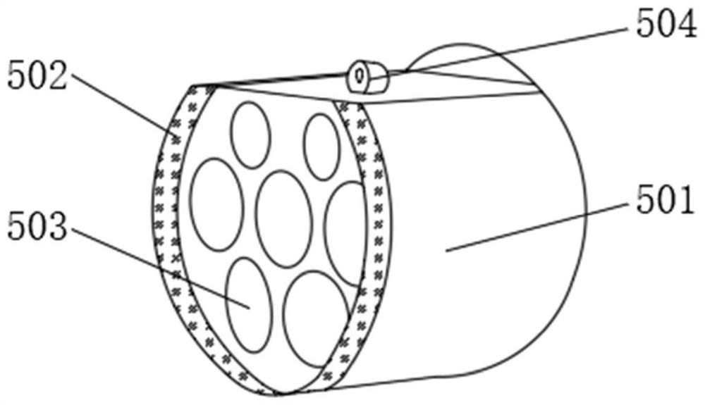
[0039] Such as figure 1 As shown, in this embodiment, the charging gun body includes a gun body 1, a grip 2, a handle 4 and a multifunctional muzzle 5, the multifunctional muzzle 5 and the grip 2 are respectively located at the front and rear ends of the gun body 1, and the handle 4 L...
Embodiment 2
[0054] On the basis of Embodiment 1, the rolling contact between the flying disc 906, the first pressing plate 910 and the squeezing plate 914 can be realized by but not limited to the following structure: the first pressing plate 910 and the flying disc 906 are on the opposite surface, the flying disc 906 and the squeezing plate The opposite surfaces of the pressing plate 914 are respectively provided with mutually cooperating balls and annular grooves, such as Figure 4 As shown, a number of first balls 930 are arranged in a circumferential array on the end face of the first pressing plate 910, and a first annular groove 911 suitable for accommodating the first balls 930 is provided on the end of the flying disc 906 facing the first pressing plate 910, and the end of the flying disc 906 facing the extrusion A plurality of second balls 908 are arranged in a circumferential array at one end of the pressing plate 914 , and a second annular groove 915 adapted to accommodate the s...
Embodiment 3
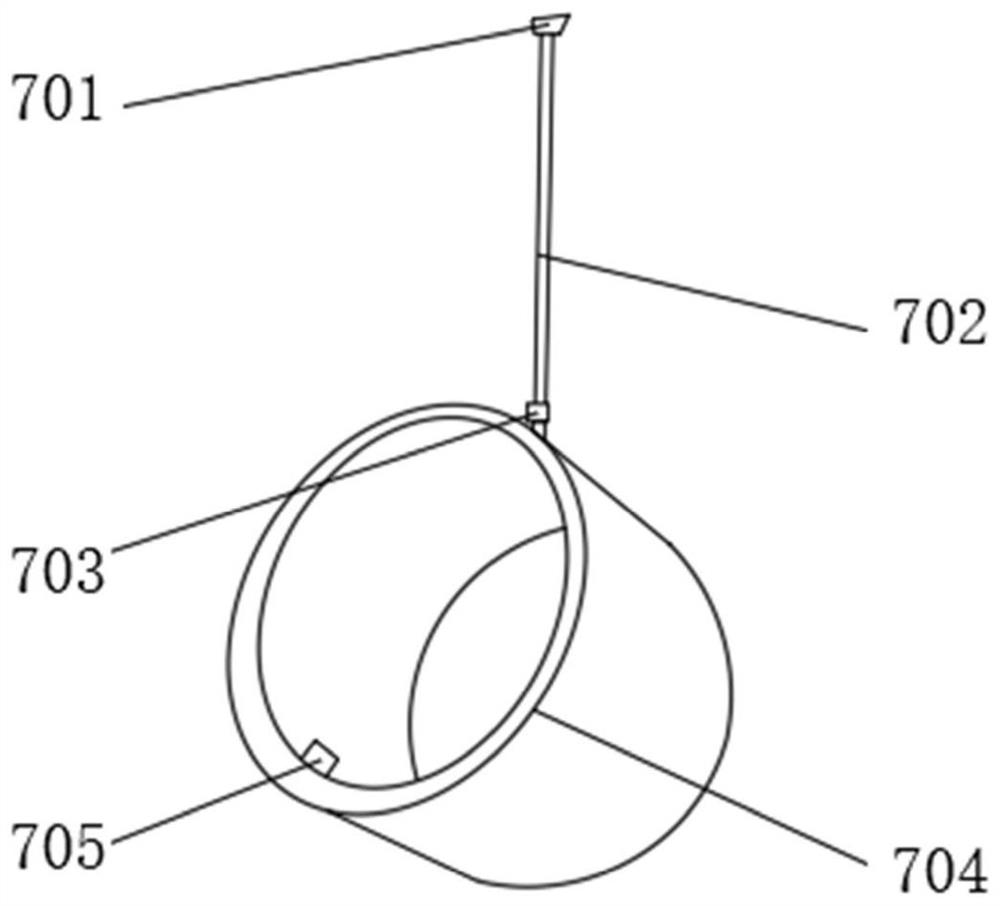
[0058] On the basis of the above-mentioned embodiments, the charging gun body also includes a protective cover 7 that is movably connected to the front end of the gun body 1, and the insulating shell 501 is provided with a buckle groove 6, and the protective cover 7 can be covered on the multi-functional muzzle 5, and Fasten with the buckle groove 6. Such as image 3 As shown, the protective cover 7 includes an insulating cover body 704 similar to a cap shape, and the insulating cover body 704 is connected to the bottom of the gun body 1 through a connecting wire 702. The upper and lower ends of the connecting wire 702 are respectively provided with an upper connecting buckle 701 and a lower connecting buckle 703 , the insulating cover 704 is fixed with the connecting wire 702 through the lower connecting buckle 703 , the gun body 1 is fixed with the connecting wire 702 through the upper connecting buckle 701 , and the buckle 705 is located on the inner surface of the insulati...
PUM
 Abstract
Description
Claims
Application Information