Turbine blade separation transverse rotation re-intersection type cooling structure

A turbine blade and cooling structure technology, applied in the direction of blade support components, engine components, machines/engines, etc., can solve the problems of low cooling effect, short flow distance, small heat exchange area of ​​cold air and trailing edge, etc., to achieve improved Cooling effect, effect of increased heat transfer area

Active Publication Date: 2021-06-11
DALIAN UNIV OF TECH
View PDF15 Cites 0 Cited by
  • Summary
  • Abstract
  • Description
  • Claims
  • Application Information

AI Technical Summary

Problems solved by technology

This type of trailing edge split cooling structure only relies on the ribs on the trailing edge to disturb the cold air, the heat exchange area between the cold air and the trailing edge is small, the flow distance is short, and the cooling effect is low

Method used


Image

  • Turbine blade separation transverse rotation re-intersection type cooling structure
  • Turbine blade separation transverse rotation re-intersection type cooling structure
  • Turbine blade separation transverse rotation re-intersection type cooling structure

Examples


Embodiment 1

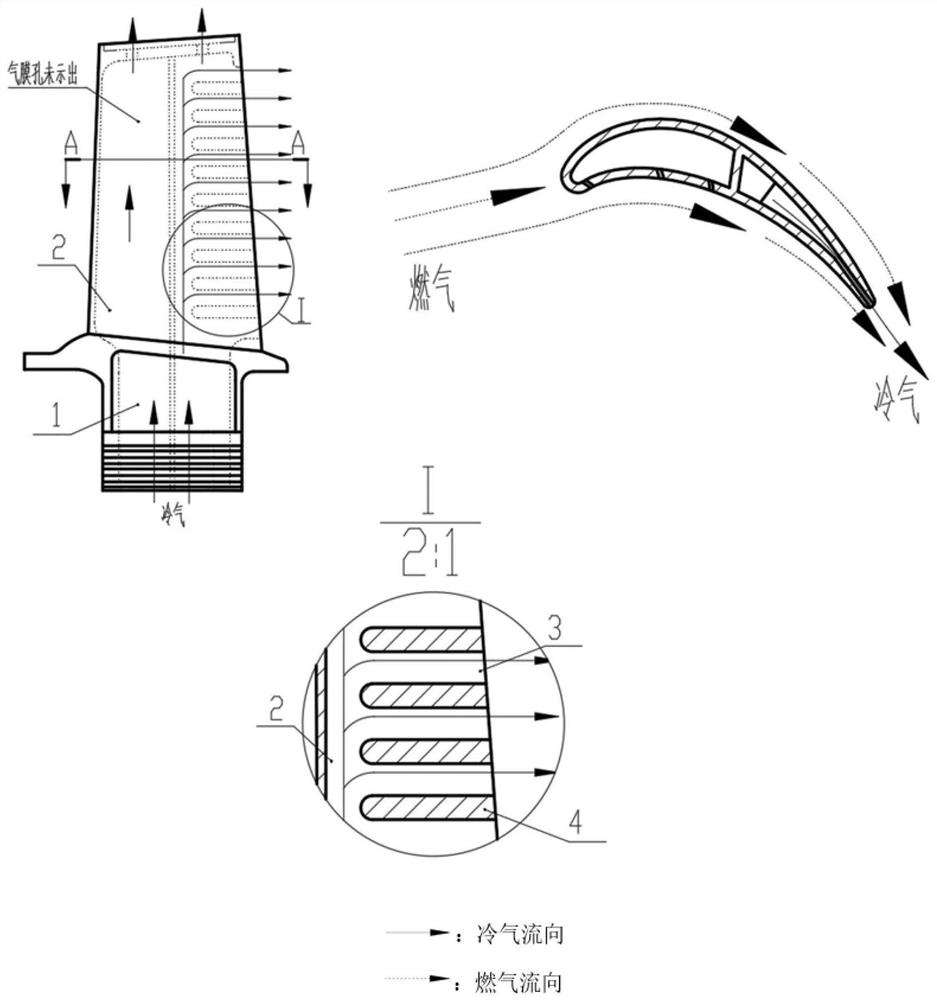
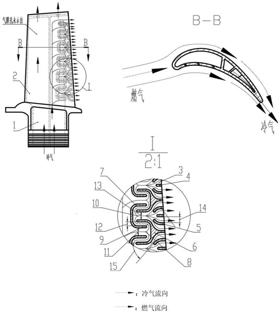
[0025] A turbine blade separation transverse rotary resetting the rehabilitation structure is mainly composed of a human font isolation rib 6, a C-shaped compact rib 7, a J-shaped bar 5, and the tail edge sewing straight rib 4 intersects, such as figure 2 Indicated.

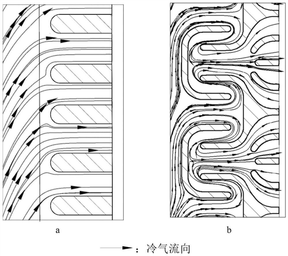
[0026] An inner chamber air passage 2 is provided inside the hollow turbine blade 1, and the low temperature cooling gas flows inside the blade and cools the blades. The tail of the blade is radially all-rounded and the line 7 and the C-shaped partial ribs 7, both interleaved combined guiding airflows to separate lateral rotation. A cold air separation passage 8 is formed between the adjacent two C-shaped ribs and its width is D. 1 = 2.4mm, the cold air is separated into two airflows flowing toward the root and the tip of the tip in the channel, and the first 180 ° rotation in the two free air rotation channels, the reverse flow direction in the direction direction . In addition to two of the ends, two cold air rotar...

Embodiment 2

[0029] The separated transverse rotary rehabilitation structure provided in the present invention can not only be used in the lower edge of the blade, or the front edge of the blade, such as Figure 4 Indicated.

[0030] The hollow turbine blade 1 is in the leading edge of the C-shaped rib 7 and the leading edge reverse C-shaped rib 17, and the interlaced combination constitutes the front return exhaust passage 16, and the airflow is guided to separate the lateral rotation. .

[0031] The adjacent two front flexible C-shaped ribs 17 form a cold air separation passage 8 and its width is D. 1 = 2.4mm, the cold air is separated into two airflows flowing toward the root and the tip of the tip in the channel, and the first 180 ° rotation in the two free air rotation channels, the reverse flow direction in the direction direction . In addition to two of the ends, two cold air rotary channels 9 are formed between each leading edge inverting C-shaped rib 17 and adjacent two C-shaped ribs 7...


PUM


Abstract

The invention belongs to the technical field of aero-engine turbine cooling, and relates to a turbine blade separation transverse rotation re-intersection type cooling structure. An inner cavity cold air channel is arranged in a hollow turbine blade of the cooling structure, and low-temperature cooling gas flows in the blade to cool the blade. Herringbone partition ribs and C-shaped partition ribs are evenly distributed on the tail edge of the blade in the radial direction and are combined in a staggered mode to guide airflow to be separated, transversely rotate and then intersect. A cold air separation channel is formed between every two adjacent C-shaped ribs, the width of the cold air separation channel is D1, cold air flows downstream in the channel and then is separated into two air flows flowing towards the blade root and the blade tip correspondingly, and the two air flows rotate by 180 degrees for the first time in two cold air rotation channels correspondingly and flow reversely in the incoming flow direction. Each strand of cold air can flow out after passing through a trailing edge crack after being turned for multiple times, and the flowing distance is increased by about 40% compared with a conventional structure, so that the utilization rate of the cold air is increased, and the temperature of the blade is reduced.

Description

Technical field [0001] The present invention belongs to the field of avionics turbine cooling technology, and involves a turbine blade separation transverse rotary rejection type cooling structure. Background technique [0002] For aerospace engine and gas turbine, increasing the temperature of the gas temperature in the turbine can greatly improve the performance of the device, but since the gas ambient temperature is much higher than the capacity of the current material, the cooling problem of the turbine blade is thus thus. At present, the hollow blade is generally used, and the heat transfer tropical heat is used in the internal strengthening of the cooling gas, and the gas film covering the gas heating is formed, which is the main solution for the problem of turbine blade cooling. At the same time, the blade "The internal heat exchange area is larger", "smaller cold air flow resistance", "higher heat transfer efficiency", "gas film coverage is more large", "smaller structura...

Claims


Application Information

Patent Timeline
Patent Type & Authority Applications(China)
IPC IPC(8): F01D5/18
CPCF01D5/186F01D5/188
Inventor 吕东刘英实韦文涛张涛孔星傲孙一楠
Owner DALIAN UNIV OF TECH
Why Eureka
Try Eureka