Air duct type cooling frequency conversion unit and layout method thereof
一种变频机组、布局方法的技术,应用在空气冷却、发动机的冷却、冷却/通风装置等方向,能够解决未见、发动机以及消声器冷却效果差等问题,达到减轻重量、好冷却效果、减少空间体积的效果
- Summary
- Abstract
- Description
- Claims
- Application Information
AI Technical Summary
Problems solved by technology
Method used
Image
Examples
Embodiment 1
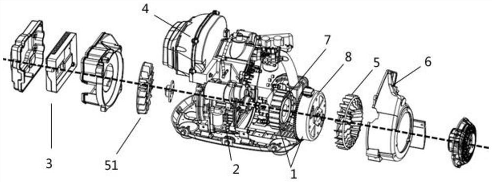
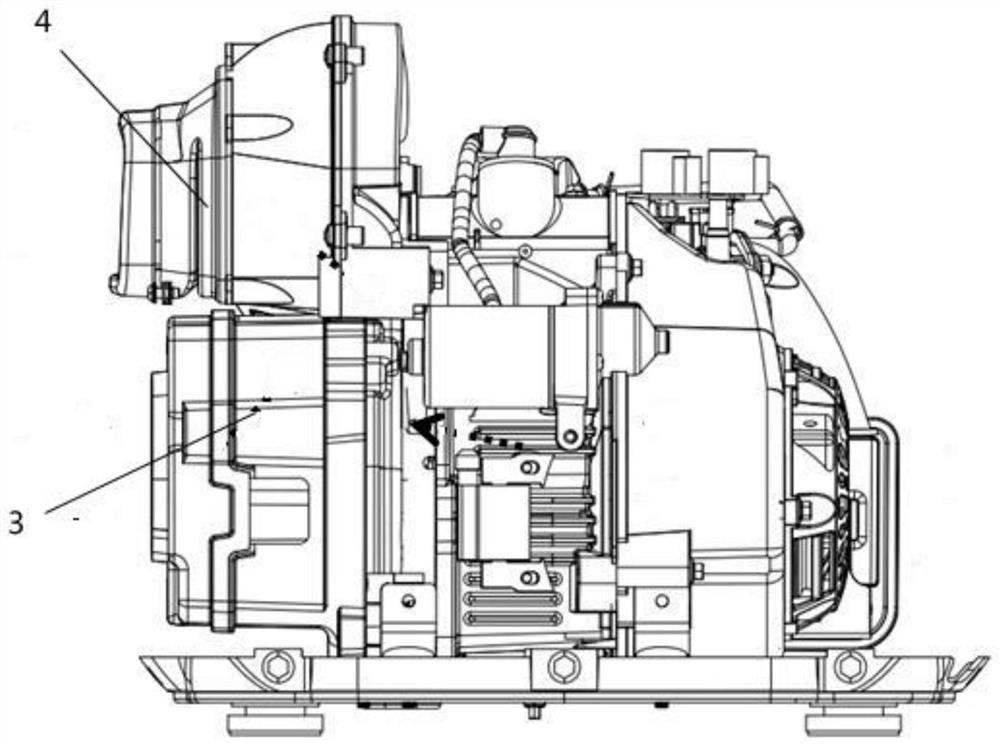
[0049] Please refer to figure 1 and figure 2 , figure 1 Schematic diagram of the explosion structure of the frequency conversion unit of the present invention. figure 2 It is a schematic diagram of the general assembly structure of an air duct cooling frequency conversion unit of the present invention. An air duct cooling frequency conversion unit, the air duct cooling frequency conversion unit includes a generator 1, an engine 2, an inverter 3, and a muffler 4; the generator 1 is installed at one end away from the muffler 4; the An engine 2 is installed on one side of the generator 1; an inverter 3 is installed on one side of the engine 2; the inverter 3 is installed at a position with the lowest temperature from the muffler 4, and the inverter 3 is installed on the muffler 4 below.
[0050] What needs to be explained in this embodiment is:
[0051] In this embodiment, the generator 1 includes a stator 7 and a rotor 8. The installation of the stator 7 and the rotor 8 n...
Embodiment 2
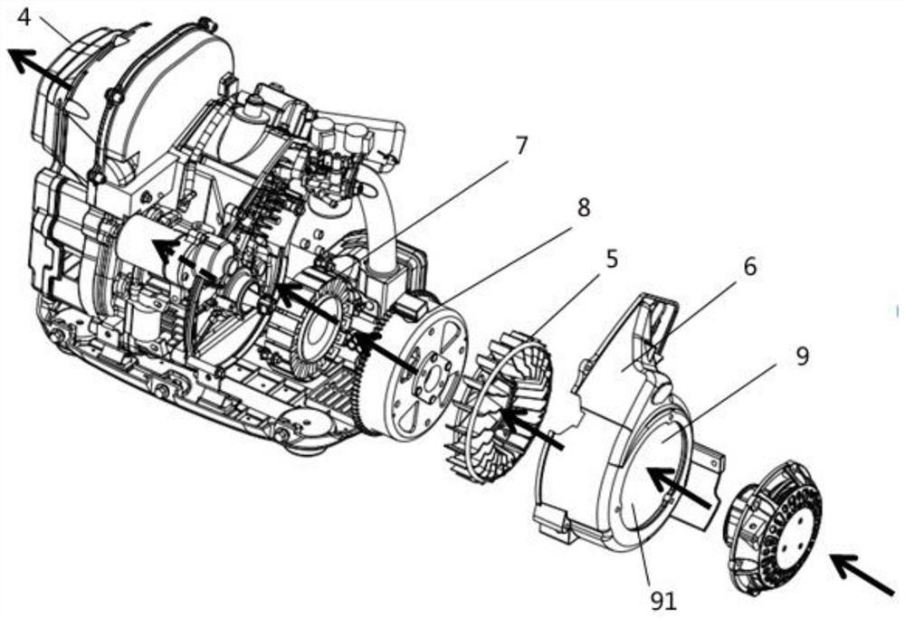
[0058] Please refer to Figure 3-Figure 5 , image 3 It is a schematic diagram of the distribution direction of the first air duct 9. Figure 4 It is a schematic diagram of the distribution direction of the second air duct 10 . Figure 5 It is a schematic diagram of the air duct distribution of the frequency conversion unit. A layout of the air duct cooling frequency conversion unit, the layout includes a first air duct 9 and a second air duct 10; the first air duct 9 flows into the generator 1 through the first air inlet 91, cooling The generator 1 enters the engine 2, then cools the engine 2, enters the muffler 4 after cooling the engine 2, and discharges the muffler 4 after being cooled; the second air inlet channel flows in from the second air inlet 101 and is cooled Afterwards, the inverter 3 merges with the first air channel 9 and flows out of the muffler 4 .
[0059] What needs to be explained in this embodiment is:
[0060] The layout of the entire frequency conve...
Embodiment 3
[0064] Please refer to Figure 6 and Figure 7 , Figure 6 It is a schematic diagram of the air duct distribution trend in Embodiment 3. Figure 7 It is the side air intake schematic diagram in embodiment 3. This embodiment is basically the same as Embodiment 2, except that a third air duct 11, a third air inlet 111, and an air inlet duct 12 are provided in this embodiment; the third air inlet 111 is directed toward the bottom of the machine side, the cooling air of the third air inlet 111 is divided into two paths, one path merges with the first air inlet 91 and flows into the first air duct 9, and the other path passes through the base of the engine 2 to dissipate heat, then enters the air inlet duct 12 and flows through the muffler 4 flow out.
[0065] What needs to be explained in this embodiment is:
[0066] The third air inlet 111 faces the bottom of the machine, and this design method has the effect of dust removal and noise reduction; the cooling air of the third ...
PUM
 Abstract
Description
Claims
Application Information
 - R&D
- Intellectual Property
- Life Sciences
- Materials
- Tech Scout
- Unparalleled Data Quality
- Higher Quality Content
- 60% Fewer Hallucinations
Browse by: Latest US Patents, China's latest patents, Technical Efficacy Thesaurus, Application Domain, Technology Topic, Popular Technical Reports.
© 2025 PatSnap. All rights reserved.Legal|Privacy policy|Modern Slavery Act Transparency Statement|Sitemap|About US| Contact US: help@patsnap.com


