

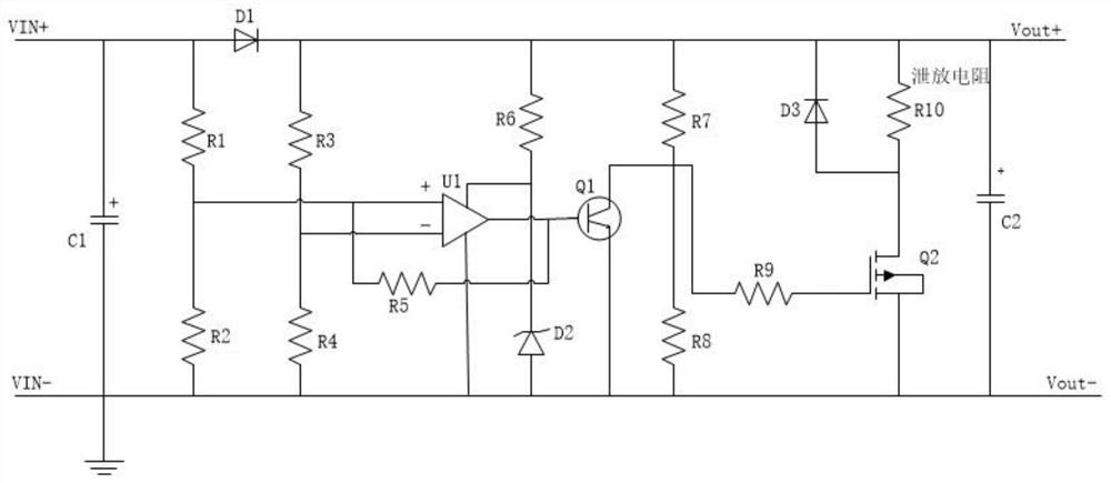
A Hysteresis Comparing Voltage Bleeding Circuit
A technology of bleeder circuit and hysteresis comparison, which is applied in the direction of electric motor/converter plug, deceleration device of DC motor, etc., to achieve the effect of reducing the number of pulses
- Summary
- Abstract
- Description
- Claims
- Application Information
AI Technical Summary
Problems solved by technology
Method used
Image

Examples
Embodiment Construction
[0016] Embodiments of the present invention are described in detail below, examples of which are shown in the drawings, wherein the same or similar reference numerals designate the same or similar elements or elements having the same or similar functions throughout. The embodiments described below by referring to the figures are exemplary and are intended to explain the present invention and should not be construed as limiting the present invention.
[0017] In conventional discharge processing, the program generally sets two comparison points, Vth1 and Vth2. When the voltage rises, Vth1 takes effect. At this time, the voltage is greater than Vth1, and the discharge will be turned on, and then the voltage will drop. In the stage where Vth1 does not take effect, Vth2 takes effect. At this time, the voltage drops below Vth2 before the discharge is disconnected. This forms a space for hysteresis comparison to prevent the discharge pipe from moving too frequently. The invention r...
PUM
 Abstract
Description
Claims
Application Information