A glaze proportioning device for ceramic processing

A technology of proportioning and ceramic processing, applied in mixer accessories, transportation and packaging, mixers, etc., can solve the problems of affecting quality, color flow, error-prone, time-consuming and labor-intensive, etc., to achieve the effect of easy collection

Active Publication Date: 2022-07-01
高安常莹新型材料有限公司
View PDF22 Cites 0 Cited by
  • Summary
  • Abstract
  • Description
  • Claims
  • Application Information

AI Technical Summary

Problems solved by technology

[0003] Generally, the staff pours various colors into the bottle of the device, and then shakes and stirs with it in the later stage to complete the deployment. This method is completely dependent on manual operation, which is time-consuming and labor-intensive. In addition, manual operation of color flow is easy to make mistakes, and the mixing ratio is uneven. Therefore, it is necessary to design a glaze ratio mixing device for ceramic processing that relies on machines to fill the device bottle without excessive manual contact and precise filling.

Method used


Image

  • A glaze proportioning device for ceramic processing
  • A glaze proportioning device for ceramic processing
  • A glaze proportioning device for ceramic processing

Examples


Embodiment 1

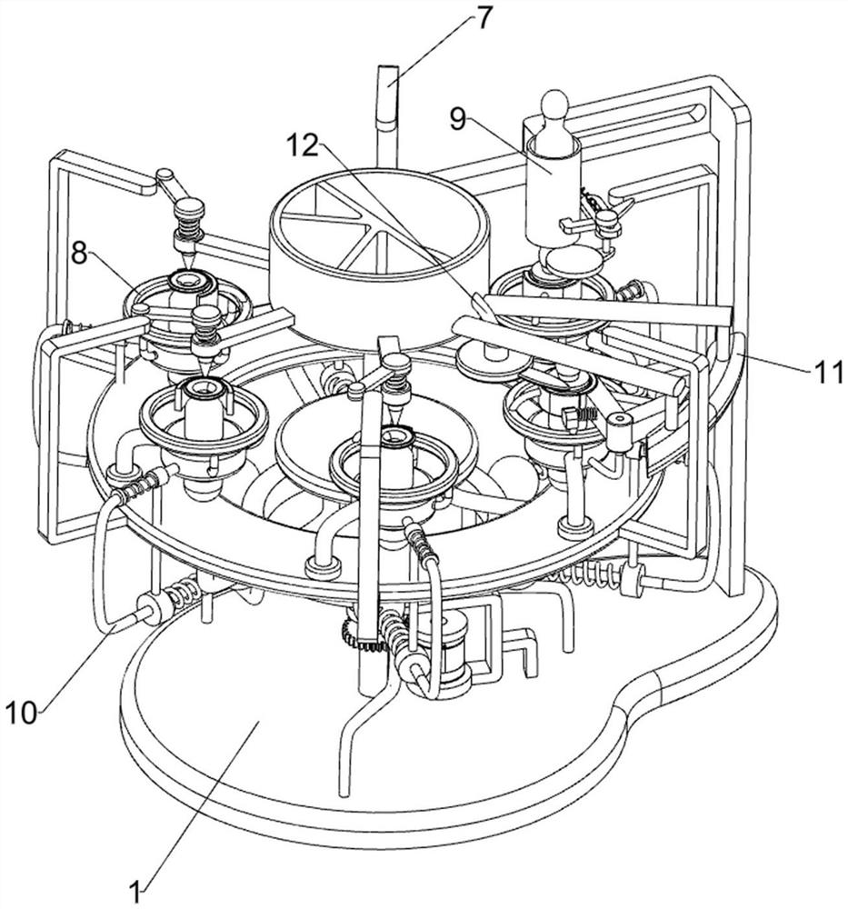
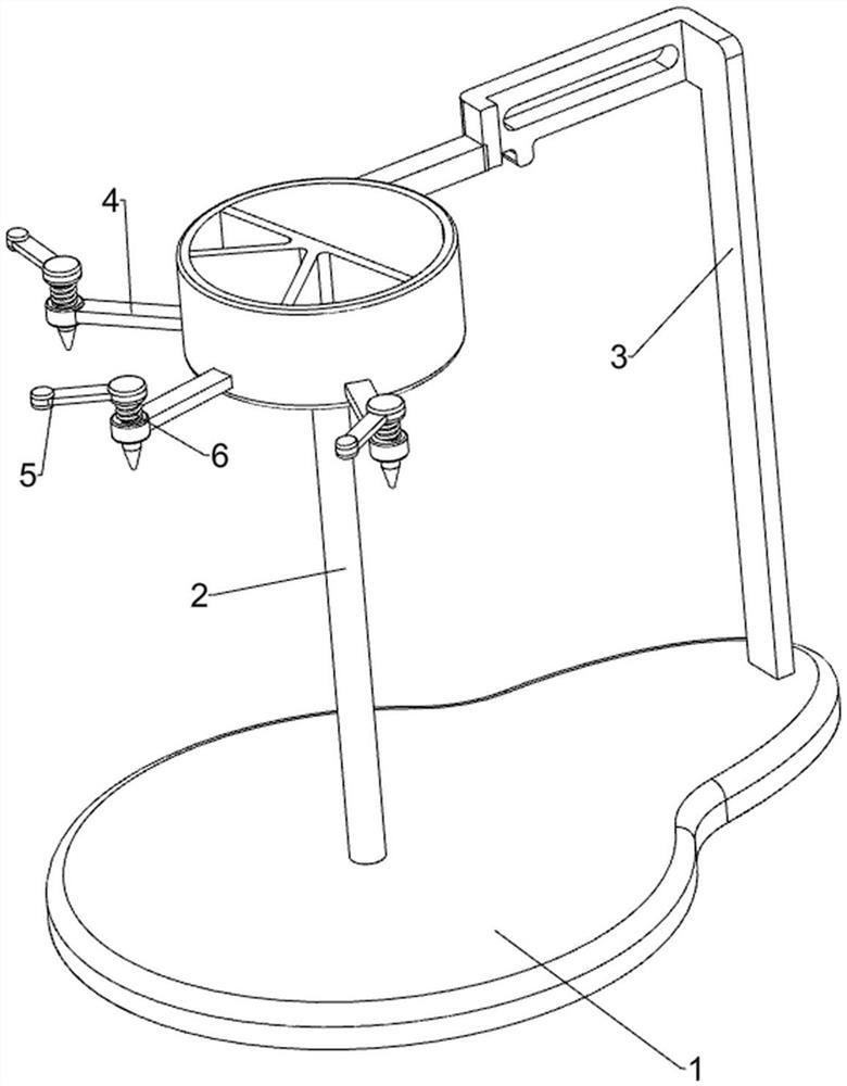
[0046] A glaze proportioning device for ceramic processing, such as figure 1 and figure 2 As shown, it includes a bottom plate 1, a first rotating shaft 2, a first fixing rod 3, a water outlet pipe 4, a switch 5, a first spring 6, a rotating mechanism 7 and a placing mechanism 8, and the top of the bottom plate 1 is rotatably provided with a first rotating shaft 2 , the top right side of the bottom plate 1 is provided with a first fixing rod 3, the upper left side of the first fixing rod 3 is connected with an adjusting frame, the adjusting frame is rotatably connected with the first rotating shaft 2, and the lower part of the adjusting frame is provided with three water outlet pipes 4, A switch 5 is rotatably provided on the outside of the top of the water pipe 4. A first spring 6 is connected between the switch 5 and the top of the water outlet pipe 4, and a rotating mechanism 7 is connected between the lower part of the first rotating shaft 2 and the bottom plate 1. Insti...

Embodiment 2

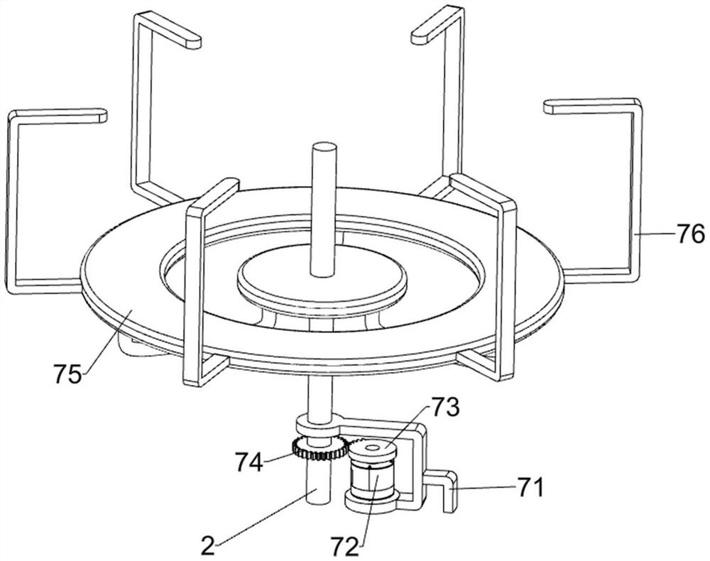
[0049] On the basis of Example 1, as image 3 and Figure 4 As shown, the rotating mechanism 7 includes a second fixed rod 71, a motor 72, a missing gear 73, a spur gear 74, a turret 75 and a touch rod 76. The top of the bottom plate 1 is provided with a second fixed rod 71. The second fixed rod 71 It is rotatably connected with the first rotating shaft 2, the second fixing rod 71 is provided with a motor 72, the output shaft of the motor 72 is provided with a missing gear 73, the lower part of the first rotating shaft 2 is connected with a spur gear 74, the spur gear 74 and the missing gear 73 In cooperation, a turret 75 is arranged in the middle of the first rotating shaft 2 , and six touch rods 76 are evenly arranged on the outer side of the turret 75 .

[0050] The placing mechanism 8 includes a third fixing rod 81, a fixing ring 82, a first fixing block 83 and a placing bottle 84. The top of the turret 75 is evenly provided with six third fixing rods 81, and the interior...

Embodiment 3

[0053] On the basis of Example 2, as Figure 5 to Figure 8 As shown, it also includes a feeding mechanism 9. The feeding mechanism 9 includes a feeding barrel 91, a guide rod 92, a stop ring 93, a telescopic block 94 and a second spring 95. The upper left side of the first fixing rod 3 is provided with a lower A guide rod 92 is provided on the front side of the lower part of the material barrel 91, the guide rod 92 is slidably provided with a blocking ring 93, the upper right side of the blocking ring 93 is provided with a telescopic block 94, and the telescopic block 94 cooperates with the touch rod 76 , a second spring 95 is connected between the upper part of the blocking ring 93 and the first fixing rod 3 .

[0054] The staff can place the placing bottle 84 in the unloading bucket 91. In the initial state, the blocking ring 93 blocks the unloading bucket 91, and the placing bottle 84 will not fall out. The block 94 is rotated forward to drive the blocking ring 93 to move ...


PUM


Abstract

The invention relates to a blending device, in particular to a glaze proportioning device for ceramic processing. Specifically, it provides a glaze proportioning device for ceramic processing that relies on a machine to fill the device bottle without excessive manual contact and accurately fills the glaze. A glaze proportioning device for ceramic processing, comprising: a bottom plate, the top of which is rotatably provided with a first rotating shaft; a first fixing rod, one side of the top of the bottom plate is provided with a first fixing rod, and the upper part of the first fixing rod is connected with a adjusting rod The water outlet pipe is provided with three water outlet pipes at the lower part of the water outlet pipe, the top of the water outlet pipe is rotatably provided with a switch, and a first spring is connected between the switch and the top of the water outlet pipe. The basic functions of the device are realized by setting up a water outlet pipe to drive the placing bottle to rotate, and at the same time, the pigments are loaded, collected, and mixed.

Description

technical field [0001] The invention relates to a blending device, in particular to a glaze proportioning device for ceramic processing. Background technique [0002] Ceramic glaze is the construction and sanitary ceramics industry that pays great attention to the use of advanced glaze technology. The glaze is divided into color glaze and colorless glaze. Building and sanitary ceramic products are generally decorated with color glaze, so that they can also be used when they are used. The admirable beauty increases the added value of the product, so it is necessary to adjust a certain proportion of the pure color glaze to make a more beautiful color glaze. [0003] Generally, the staff fills various colors into the bottle of the device, and then shakes and stirs with it later to complete the preparation. This method completely relies on manual operation, which is time-consuming and labor-intensive, and the manual operation of the color flow is prone to errors, and the proport...

Claims


Application Information

Patent Timeline
Patent Type & Authority Patents(China)
IPC IPC(8): B01F31/00B01F35/71B01F35/80B01F35/42B01F35/40B02C18/06B02C18/18B02C18/24B01F101/30
CPCB02C18/06B02C18/18B02C18/24B01F33/00B01F35/40B01F35/42B01F35/711B01F35/71B01F35/80
Inventor 全春辉
Owner 高安常莹新型材料有限公司
Why Eureka
Try Eureka