High-precision optical lens polishing machine and damping mechanism and upper grinding device of high-precision optical lens polishing machine

A technology for optical lenses and grinding devices, which is applied in the direction of grinding drive devices, optical surface grinders, grinding/polishing equipment, etc., and can solve problems such as difficulties in discharging and retrieving materials, unfavorable production and processing, and long time required for lifting , to achieve the effect of being convenient for production, processing and replacement, conducive to production and processing, and convenient to take and discharge materials

Pending Publication Date: 2021-06-15
鹤山市嘉米基光电科技有限公司
View PDF12 Cites 0 Cited by
  • Summary
  • Abstract
  • Description
  • Claims
  • Application Information

AI Technical Summary

Problems solved by technology

[0005] 1. During the grinding process, due to the irregular surface of the workpiece, the grinding disc vibrates. If the grinding disc is completely fixed, the impact generated by the vibration will affect the grinding disc. If it is used for a long time, it is easy to damage the grinding disc
[0006] 2. The upper grinding device and the main shaft in the traditional polishing machine are always connected, and the upper grinding device and the lower grinding device cannot be separated, resulting in difficulties in discharging and retrieving materials, which is not conducive to pr

Method used


Image

  • High-precision optical lens polishing machine and damping mechanism and upper grinding device of high-precision optical lens polishing machine
  • High-precision optical lens polishing machine and damping mechanism and upper grinding device of high-precision optical lens polishing machine
  • High-precision optical lens polishing machine and damping mechanism and upper grinding device of high-precision optical lens polishing machine

Examples


Embodiment Construction

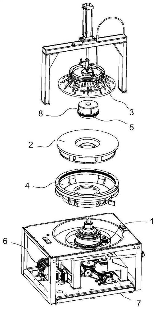
[0035] Such as figure 1As shown, a high-precision polishing machine for optical lenses, the polishing machine includes a frame and a power transmission device 1 installed on the frame, a lower grinding device 2, an upper grinding device 3, an upper grinding clutch device 8, a large ring gear device 4, A pinion gear arrangement 5 , a first motor 6 and a second motor 7 . The power transmission device 1 is arranged below the frame, and the upper grinding clutch device 8, the small ring gear device 5, the lower grinding device 2 and the large ring gear device 4 are installed on the power transmission device 1 sequentially from top to bottom. The upper grinding device 3 is vertically lifted and arranged on the top of the frame, and the upper grinding device 3 is positioned directly above the lower grinding device 2 . The bottom of the upper grinding device 3 cooperates with the upper grinding clutch device 8, and the upper grinding clutch device 8 controls the upper grinding devic...


PUM


Abstract

The invention relates to the technical field of optical lens machining, in particular to a high-precision optical lens polishing machine and a damping mechanism and an upper grinding device of the high-precision optical lens polishing machine. The high-precision optical lens polishing machine comprises a mounting rod, a radial spherical plain bearing, a round nut, a spherical plain bearing pressing plate and a spherical plain bearing cover plate; the mounting rod is vertically arranged, the radial spherical plain bearing is rotationally arranged on the mounting rod, the lower end face of the radial spherical plain bearing is attached to a shaft shoulder on the lower part of the mounting rod, the round nut is mounted on the mounting rod through threaded connection, a gap is formed between the round nut and the upper end face of the radial spherical plain bearing in a reserved mode, the upper part of the spherical plain bearing pressing plate abuts against the bottom of the radial spherical plain bearing, the bottom of the spherical plain bearing cover plate abuts against the top of the spherical plain bearing pressing plate, the inner side face of the spherical plain bearing cover plate is attached to the outer side face of the radial spherical plain bearing, and the upper part of the spherical plain bearing cover plate is pressed on the upper end face of the radial spherical plain bearing. According to the high-precision optical lens polishing machine and the damping mechanism and the upper grinding device of the high-precision optical lens polishing machine, the influence of vibration on an upper millstone can be reduced, and the service life is prolonged.

Description

technical field [0001] The invention relates to the technical field of optical lens processing, in particular to a high-precision optical lens polishing machine, a shock-absorbing mechanism and an upper grinding device. Background technique [0002] Polishing machines, also known as grinders, are often used for mechanical grinding, polishing and waxing. Its working principle is: the motor drives the sponge or wool polishing disc installed on the polishing machine to rotate at high speed. Due to the joint action of the polishing disc and the polishing agent and friction with the surface to be polished, it can achieve the effect of removing paint surface pollution, oxide layer and shallow marks. Purpose. The rotational speed of the polishing disc is generally 1500-3000 r / min, mostly continuously variable. [0003] Existing polishing machines, such as the Chinese utility model patent (publication number: CN205033069U, publication date: 20160217) disclose a double-sided grindi...

Claims


Application Information

Patent Timeline
IPC IPC(8): B24B13/00B24B41/00B24B41/04B24B47/12B24B47/00B24B57/02
CPCB24B13/00B24B41/007B24B41/04B24B47/12B24B47/00B24B57/02Y02P70/10
Inventor 王毛王成高唐晚雄
Owner 鹤山市嘉米基光电科技有限公司
Why Eureka
Try Eureka