Orbital ring rotary flapping wing power device

A technology of power device and orbital ring, which is applied in the field of orbital ring rotating flapping wing power device, can solve the problems of impossibility of large-scale promotion and use, collision between propeller and surrounding objects, ignition of surrounding objects, etc., to achieve the expansion and reduction of blades Small area, low cost, and the effect of reducing resistance

Pending Publication Date: 2021-06-15
杭州宝桐科技有限公司
View PDF0 Cites 0 Cited by
  • Summary
  • Abstract
  • Description
  • Claims
  • Application Information

AI Technical Summary

Problems solved by technology

[0003] However, the above vertical take-off and landing aircraft has no way to promote and use it in a large area due to its own insurmountable shortcomings.
For example, a tiltrotor that uses a large propeller as a power plant for vertical take-off and landing and level flight, although it has good performance in terms of take-off and landing carrying capacity and level flight speed, its huge propeller can only be used in open and relatively flat areas. When used in a small space or a place with many obstacles, such as between buildings and streets, it cannot be deployed, and it is easy to cause the propeller to collide with surrounding objects.
Although the vertical take-off and landing scheme based on jet engine power has low requirements on the use of space, its thrust energy efficiency is low, and at the same time, the exhaust gas generated by high-temperature and high-pressure injection will cause damage to nearby objects; the energy efficiency of this vertical take-off and landing method It is relatively low and has a high risk of use. The jet wake is likely to cause the ground to scorch or ignite surrounding objects, so it has high requirements for the take-off and landing site, and cannot be used in other places.

Method used


Image

  • Orbital ring rotary flapping wing power device
  • Orbital ring rotary flapping wing power device
  • Orbital ring rotary flapping wing power device

Examples


Embodiment Construction

[0021] The present invention will be described in detail below in conjunction with the accompanying drawings.

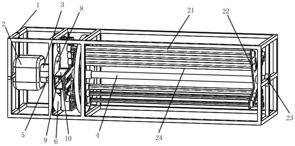
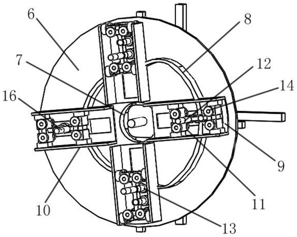
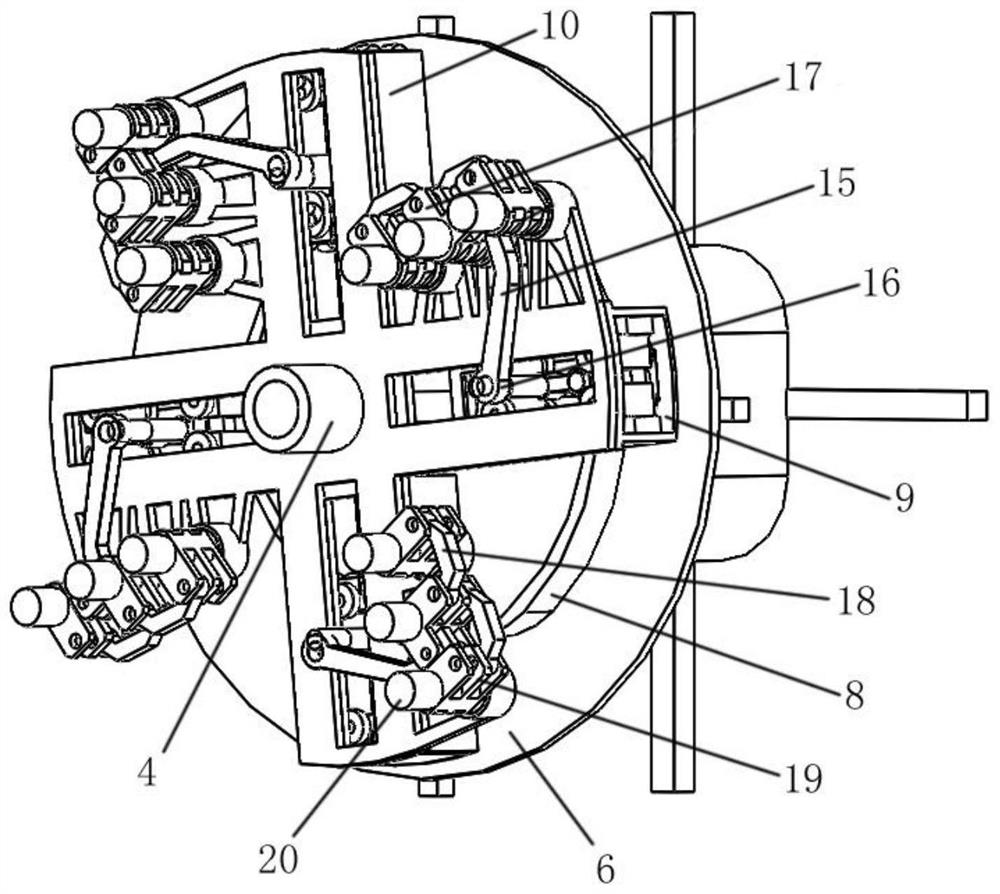
[0022] Such as figure 1 , figure 2 , image 3 , Figure 4 As shown, the orbital ring rotary flapping wing power device of the present invention consists of a support 1, an engine 2, a coupling 3, a main shaft 4, an orbital ring support frame 5, an orbital ring connector 6, an orbital ring connecting bearing 7, a core orbital ring 8, Sliding sleeve 9, sliding sleeve support 10, slider 11, slider shaft 12, slider shaft bearing 13, small pulley 14, active rocker arm 15, active rocker arm bearing 16, central axis connection block 17, driven rocker arm 18, It consists of a shaft connection block 19, a blade distribution wheel 20, a blade 21, a blade bracket 22, a blade distal bearing 23, and a segmented self-assembled fan blade 24.

[0023] Among them, the engine 2 is fixed on the bracket 1, the engine rotating shaft is connected with the coupling 3, the coupling 3, ...


PUM


Abstract

An orbital ring rotary flapping wing power device is composed of a support, an engine, a coupler, a main shaft, an orbital ring supporting frame, an orbital ring connecting body, an orbital ring connecting bearing, a core orbital ring, a sliding sleeve, a sliding sleeve support, a sliding block, a sliding block shaft, a sliding block shaft bearing, a small pulley, a driving rocker arm, a driving rocker arm bearing, a middle shaft connecting block, a driven rocker arm, a driven shaft connecting block, a blade distribution wheel, blades, a blade support, a blade far-end bearing and a sectional type self-combination fan blade. The orbital ring rotary flapping wing power device can effectively provide vertical take-off and landing power for an aircraft, has the advantages of being high in power generation efficiency, good in control effect, low in cost, wide in application scene and the like, and has very positive effects.

Description

technical field [0001] The invention belongs to a reversing power device, in particular to an orbit ring rotating flapping wing power device. Background technique [0002] Vertical take-off and landing technology is a technology that can take off and land without sliding; vertical take-off and landing aircraft reduce or basically get rid of the dependence on the runway, and only need a small flat ground to stand up and land vertically. It can make the aircraft fly and configure, which is convenient for flexible attack, transfer and camouflage concealment, and improves the survival rate of the aircraft battlefield; vertical take-off and landing aircraft can be roughly divided into rotor aircraft, jet engine thrust steering aircraft, tilt rotor aircraft, tail seat propeller powered aircraft , Ducted fan powered aircraft. [0003] But above VTOL vehicle has no way to popularize and use in a large area because of its own insurmountable shortcomings. For example, a tiltrotor th...

Claims


Application Information

Patent Timeline
Patent Type & Authority Applications(China)
IPC IPC(8): B64C33/02B64C29/00
CPCB64C29/00B64C33/02
Inventor 张旭生陈晓春陈成立方婷梁自成
Owner 杭州宝桐科技有限公司
Why Eureka
Try Eureka