
Electroplating device

An electroplating device and electrolytic cell technology, applied in the electrolysis process, electrolysis components, cells, etc., can solve the problems of affecting material unloading, accidental contact with electrolyte, time-consuming and laborious, etc., to achieve smooth sliding, increase safety, and increase unloading. The effect of efficiency

Pending Publication Date: 2021-06-15
吴正鑫
View PDF0 Cites 3 Cited by
  • Summary
  • Abstract
  • Description
  • Claims
  • Application Information

AI Technical Summary

Problems solved by technology

[0003] Generally, when parts are electroplated, the parts are directly poured into the electrolytic tank for electroplating. When the electroplated parts are salvaged later, it is troublesome, time-consuming and laborious, and may also cause the operator to touch the electrolytic tank by mistake. In the case that the liquid causes skin damage, the general hanging electroplating still needs to be suspended and removed manually, but the electroplated parts contain a large amount of electrolyte, which will be harmful when taken manually. After the completion, it needs to be placed in a special collection box. If it cannot be removed and dropped directly, it will cause low efficiency. Some material receiving devices with material receiving plates may directly accumulate materials due to the direct fall of materials. The situation on the receiving plate seriously affects the cutting of materials

Method used


Image

  • Electroplating device
  • Electroplating device
  • Electroplating device

Examples


Embodiment Construction

[0025] In order to make the technical means, creative features, goals and effects achieved by the present invention easy to understand, the present invention will be further described below in conjunction with specific embodiments.

[0026] It should be noted that the terms "first" and "second" in the description and claims of the present application and the above drawings are used to distinguish similar objects, but not necessarily used to describe a specific sequence or sequence. It should be understood that the data so used may be interchanged under appropriate circumstances for the embodiments of the application described herein. Furthermore, the terms "comprising" and "having", as well as any variations thereof, are intended to cover a non-exclusive inclusion, for example, a process, method, system, product or device comprising a sequence of steps or elements is not necessarily limited to the expressly listed instead, may include other steps or elements not explicitly lis...


PUM


Abstract

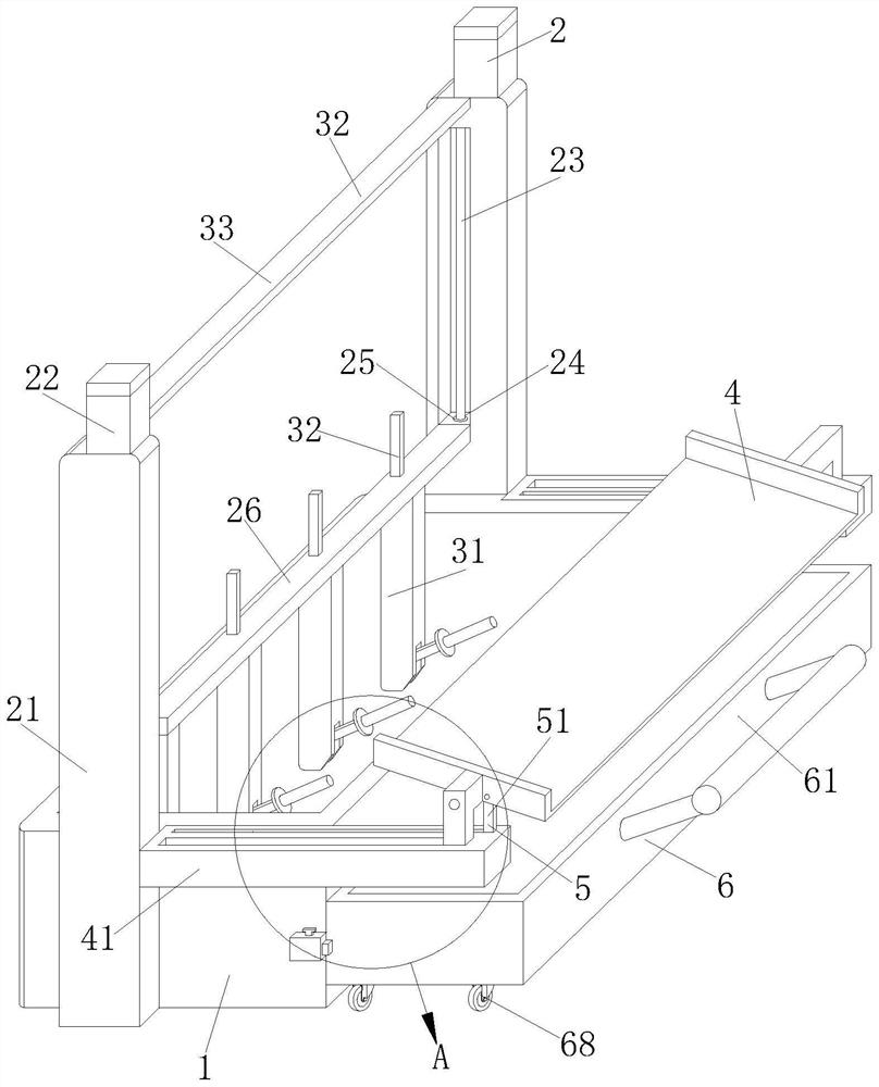
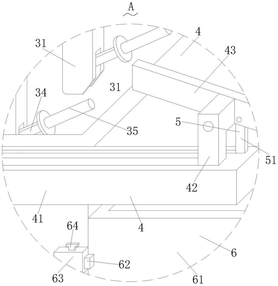
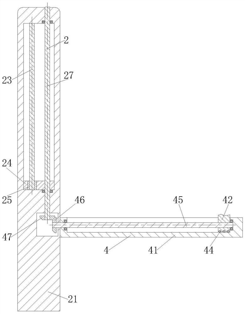
The invention relates to the field of electroplating devices, and particularly discloses an electroplating device. The electroplating device comprises an electrolytic tank, a lifting structure, a discharging structure, a receiving structure, a shaking structure and a collecting structure. The lifting structure is arranged outside the electrolytic tank, so that suspended to-be-electroplated parts can be automatically put into the electrolytic tank for electrolysis, the parts can be automatically pulled out of the electrolytic tank after electroplating of the parts is completed, manual operation is not needed, the feeding and discharging efficiency can be improved, and skin injuries caused by contact with an electrolyte can be avoided; in the process that the parts are pulled out of the electrolytic tank through the lifting structure, the discharging structure can be synchronously driven to work, rapid discharging can be achieved through automatic discharging work of the discharging structure, the discharging efficiency can be improved, and skin injuries caused by mistaken contact with the electrolyte due to manual discharging can be avoided; and the lifting structure can synchronously drive the receiving structure to work in the vertical lifting process of the parts.

Description

technical field [0001] The invention relates to an electroplating device technology, in particular to an electroplating device, which belongs to the field of electroplating devices. Background technique [0002] Electroplating is the process of plating a thin layer of other metals or alloys on the surface of certain metals using the principle of electrolysis. It is a process of using electrolysis to attach a layer of metal film to the surface of metal or other material parts to prevent metal oxidation ( Such as rust), improve wear resistance, electrical conductivity, reflective properties, corrosion resistance (copper sulfate, etc.) and enhance the appearance. The outer layer of many coins is also electroplated. During electroplating, the plated metal or other insoluble materials are used as the anode, and the workpiece to be plated is used as the cathode, and the cations of the plated metal are reduced on the surface of the workpiece to be plated to form a coating. In ord...

Claims


Application Information

Patent Timeline
Patent Type & Authority Applications(China)
IPC IPC(8): C25D17/00C25D21/00
CPCC25D17/00C25D21/00
Inventor 吴正鑫冯捷
Owner 吴正鑫
Learn More