River channel desilting device for water conservancy project

A technology for dredging equipment and water conservancy projects, which is applied to earth movers/shovels, mechanically driven excavators/dredgers, construction, etc. It can solve the problem of decreased shipping capacity, easy adhesion of silt to the reamer, and increased Flood control difficulties and other issues

Inactive Publication Date: 2021-06-15
杨志洋
View PDF0 Cites 4 Cited by
  • Summary
  • Abstract
  • Description
  • Claims
  • Application Information

AI Technical Summary

Problems solved by technology

[0002] In addition to hindering river navigation and causing a decrease in shipping capacity, river siltation is the main hazard that reduces river flood discharge capacity, aggravates flood disasters, and increases flood control difficulties.
[0003] The cutter suction dredger is a commonly used dredging tool. It uses a reamer to mix the silt at the bottom of the river with the river water to form mud, and then discharges the mud through the mud discharge pipe. However, it is difficult to mix the mud with the river water to form mud. , the sludge is lumpy, and it is easy to block the sludge discharge pipe. At the same time, the sludge is easy to adhere to the reamer, which will affect the mixing effect of the sludge and the river water.

Method used


Image

  • River channel desilting device for water conservancy project
  • River channel desilting device for water conservancy project
  • River channel desilting device for water conservancy project

Examples


Embodiment Construction

[0029] The following will clearly and completely describe the technical solutions in the embodiments of the present invention with reference to the accompanying drawings in the embodiments of the present invention. Obviously, the described embodiments are only some, not all, embodiments of the present invention. Based on the embodiments of the present invention, all other embodiments obtained by persons of ordinary skill in the art without making creative efforts belong to the protection scope of the present invention.

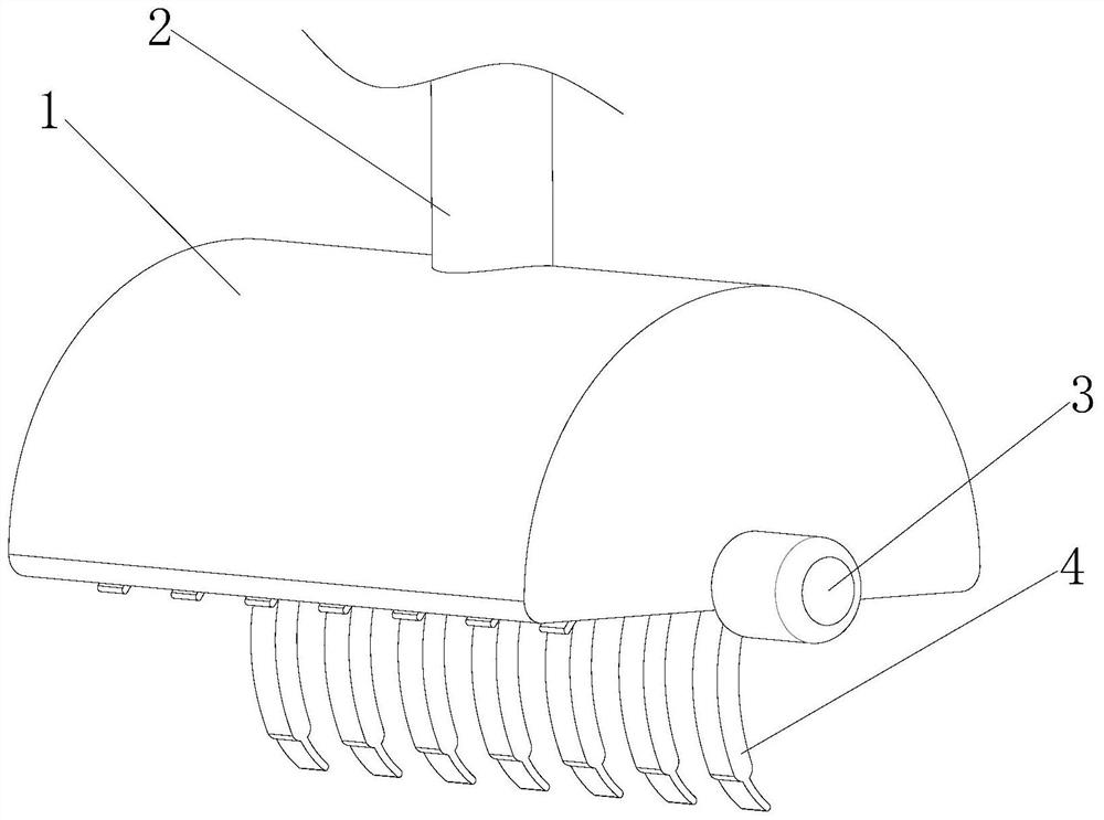
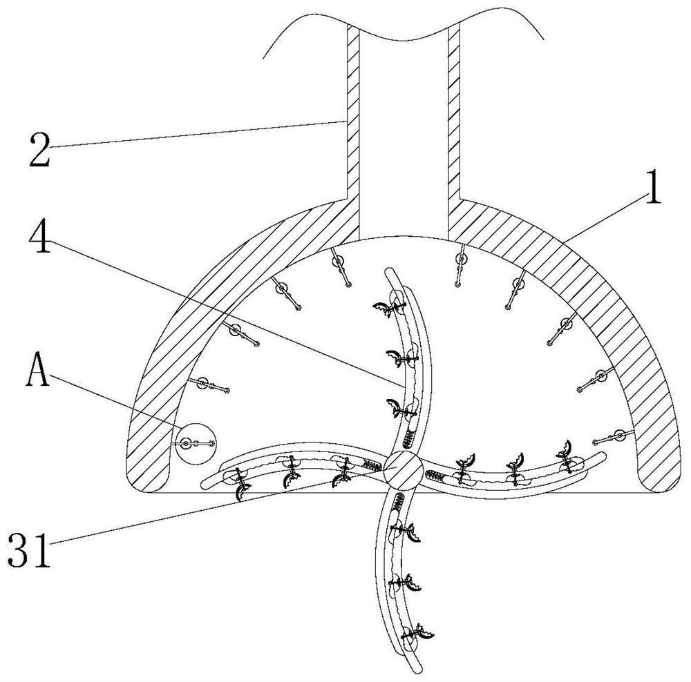
[0030] see Figure 1-7 , the present invention provides a technical solution: a river dredging device for water conservancy projects, comprising a protective cover 1, a mud discharge pipe 2, a motor 3 and a rotating shaft 31, and the mud discharge pipe 2 is fixedly installed on the upper end of the protective cover 1, The motor 3 is fixedly mounted on one side of the protective cover 1, the rotating shaft 31 is fixedly connected to the output end of the motor ...


PUM


Abstract

The invention relates to the technical field of hydraulic engineering, and discloses a river channel dredging device for water conservancy project. The device comprises a protective cover, a sludge discharge pipe, a motor and a rotating shaft, the sludge discharge pipe is fixedly mounted at the upper end of the protective cover, the motor is fixedly mounted on one side of the protective cover, the rotating shaft is fixedly connected to an output end of the motor, the rotating shaft is inserted into the interior of the protective cover, a stirring mechanism is arranged on the rotating shaft, a beating mechanism is arranged on the inner wall of the protective cover, the stirring mechanism comprises a stirring rod, a compression spring, a compression rod and a silt fishing mechanism, the stirring rod is fixedly installed on the rotating shaft, a pressing groove is formed in the interior of the stirring rod, the compression rod is connected with the stirring rod through the pressing groove in a sliding mode, and the compression spring is fixedly installed in the pressing groove. According to the device, the purpose of rotating the stirring rod is achieved, so that sludge at the river bottom can also form slurry through rotation of the stirring rod, and the purpose of dredging is achieved by adsorbing the slurry through the sludge discharge pipe.

Description

technical field [0001] The invention relates to the technical field of water conservancy engineering, in particular to a river dredging device for water conservancy engineering. Background technique [0002] In addition to hindering river navigation and causing a decrease in shipping capacity, river siltation is the main hazard that reduces river flood discharge capacity, aggravates flood disasters, and increases flood control difficulties. [0003] The cutter suction dredger is a commonly used dredging tool. It uses a reamer to mix the silt at the bottom of the river with the river water to form mud, and then discharges the mud through the mud discharge pipe. However, it is difficult to mix the mud with the river water to form mud. , The silt is lumpy, and it is easy to block the mud discharge pipe. At the same time, the silt is easy to adhere to the reamer and affect the mixing effect of the silt and river water. Contents of the invention [0004] The object of the pres...

Claims


Application Information

Patent Timeline
Patent Type & Authority Applications(China)
IPC IPC(8): E02F5/28E02F3/88E02F3/92
CPCE02F3/88E02F3/9237E02F3/9293E02F5/282
Inventor 不公告发明人
Owner 杨志洋
Why Eureka
Try Eureka