Rotation aeration ejector and control system thereof

A control system and ejector technology, applied in water aeration, chemical instruments and methods, sustainable biological treatment, etc., can solve problems such as difficulty in manual dredging, insufficient height space, high labor intensity, etc., to increase the oxygen content of sewage volume, improve dredging efficiency, and reduce labor intensity

Pending Publication Date: 2019-10-25
南京中来环保设备有限公司
View PDF0 Cites 0 Cited by
  • Summary
  • Abstract
  • Description
  • Claims
  • Application Information

AI Technical Summary

Problems solved by technology

[0004] Commonly used flushing equipment for rain and flood storage tanks includes flushing doors and flushing hydraulic dumps, etc. The flushing doors need to divide the storage pond into several flushing corridors for flushing separately, and the accumulated water can only be flushed once each time. It is limited to the shape of the pool. For example, when the pool is round or irregular, the above equipment cannot be used, or the design of the flushing corridor needs to avoid the support columns in the pool, otherwise the flushing effect will be greatly affected. If you stay For a long time, the silt is too thick and too thick to be washed away. Over time, in severe cases, the function of the rainwater storage tank may be lost and eventually abandoned; the flushing hydraulic tipping bucket and the flushing door are a one-time flushing process, and the flushing hydraulic tipping bucket is installed A certain height is required to generate sufficient scouring force, and the municipal pipe network often has insufficient height space, which greatly limits the scope and effect of hydraulic dumping
[0005] Manual dredging is labor-intensive and highly hazardous, and rain and flood storage tanks are mostly built underground, making manual dredging difficult
Long-term siltation will also lead to the death, decay and odor of organic matter, which will affect the environment, and at the same time, it will easily lead to the accumulation of harmful gases, posing a threat to the safety of dredging workers

Method used


Image

  • Rotation aeration ejector and control system thereof

Examples


Embodiment Construction

[0017] In order to make the object, technical solution and advantages of the present invention clearer, the present invention is described below through specific embodiments shown in the accompanying drawings. It should be understood, however, that these descriptions are exemplary only and are not intended to limit the scope of the present invention. Also, in the following description, descriptions of well-known structures and techniques are omitted to avoid unnecessarily obscuring the concept of the present invention.

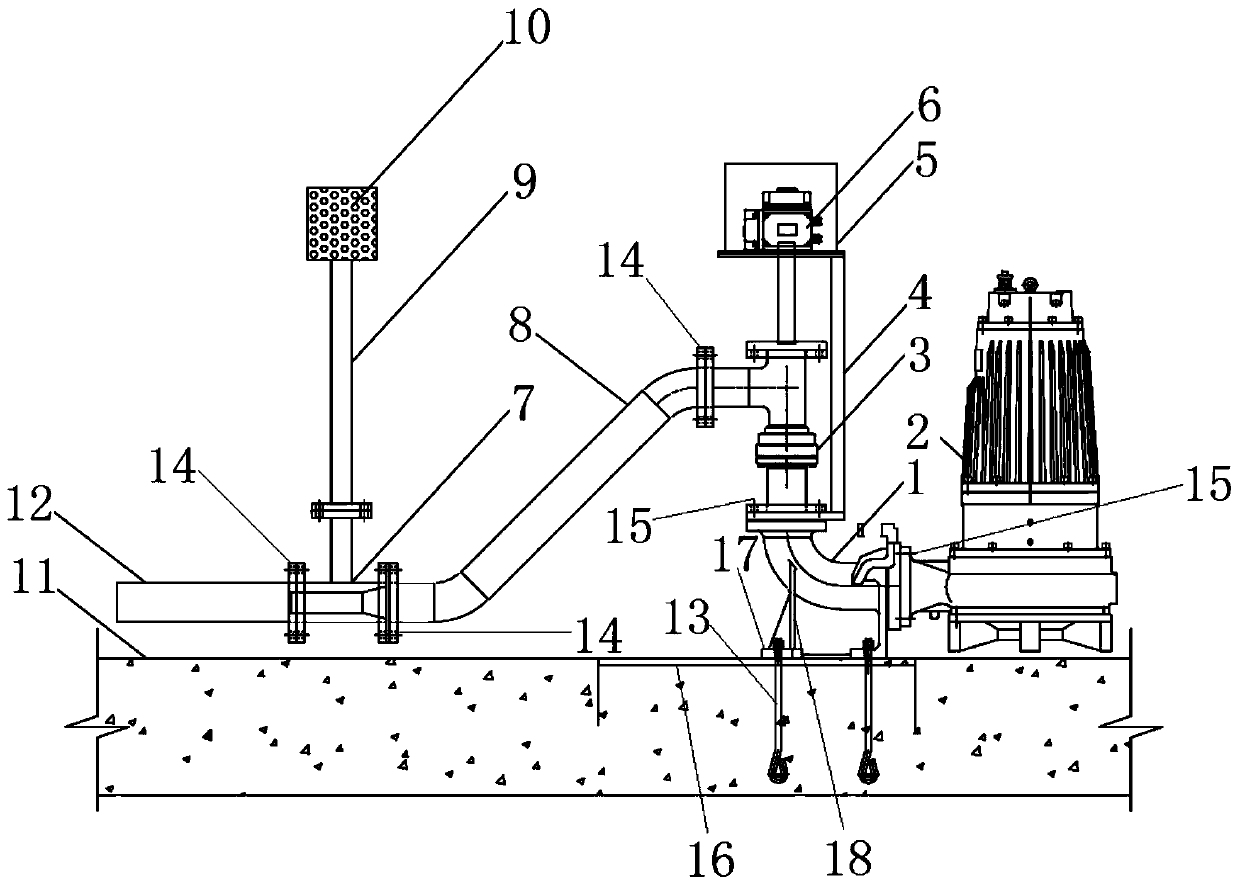
[0018] Such as figure 1 As shown, a rotary aeration injector and its control system, the structure includes: an auto-coupling mechanism 1, a power pump 2, a rotary tee joint 3, a fixing mechanism 4, a protective cover 5, a steering drive mechanism 6, and an air mixing box 7. Power pipe 8, air intake pipe 9, filter screen 10, pool bottom floor 11, aeration outlet pipe 12, anchor bolt 13, flange 14, connecting bolt 15, the self-coupling mechanism 1 includes: ba...


PUM


Abstract

The invention discloses a rotation aeration ejector and a control system thereof. The rotation aeration ejector comprises a base, a guide rod support and a guide rod; the base is fixedly mounted on afloor at the bottom of a pool through foundation bolts, the guide rod base is mounted on the base through foundation bolts, and the guide rod is welded to the guide rod base; a power pump is mounted at the right end of a self-coupling mechanism through connecting bolts, and a rotating tee joint is mounted at the top end of the self-coupling mechanism through connecting bolts; a steering driving mechanism is mounted at the top end of the rotating tee joint and fixed to the self-coupling mechanism through a fixing mechanism; the right end of a power pipeline is mounted on the rotating tee jointthrough flanges, and a mixed gas box is mounted at the outlet end of the power pipeline through flanges; and an aeration outlet pipe is mounted at the outlet end of the mixed gas box through flanges,a gas inlet pipeline communicates with the mixed gas box, and a filter net is mounted at the top end of the gas inlet pipeline. The rotation aeration ejector and the control system are scientific andreasonable in design, simple in structure and convenient to operate.

Description

Technical field: [0001] The invention relates to a rotary aeration injector and its control system, belonging to the technical field of aeration injectors. Background technique: [0002] In the prior art, when urban rainfall exceeds the water delivery capacity of urban drainage pipes, local deep water accumulation (inner waterlogging) will occur in the city. The rainwater with the transport capacity is stored in the rain and flood storage tank. After the rainfall is over, the rainwater in the rain and flood storage tank is discharged through the submersible sewage pump, thereby preventing urban waterlogging. [0003] Such storage tanks can also be installed at the entrance of the sewage treatment plant. After the peak water consumption, the inflow of the sewage treatment plant will exceed the design load. In order to avoid the direct discharge of excess sewage, the storage tank Storing overloaded sewage and leaving it for treatment when the inflow is low can effectively red...

Claims


Application Information

Patent Timeline
Patent Type & Authority Applications(China)
IPC IPC(8): C02F7/00C02F3/02
CPCC02F3/02C02F7/00C02F2103/007Y02W10/10
Inventor 王小虎
Owner 南京中来环保设备有限公司
Why Eureka
Try Eureka