Eureka AIR delivers breakthrough ideas for toughest innovation challenges, trusted by R&D personnel around the world.

Drainage pipeline desilting device

A technology for dredging devices and drainage pipes, which is used in water supply devices, cleaning sewer pipes, waterway systems, etc., can solve problems such as poor practicability, inability to break dirt, and inability to stir drainage pipes, and achieve the effect of improving efficiency and quality.

Pending Publication Date: 2021-11-30
长兴骋旭市政道路设施有限公司
View PDF0 Cites 0 Cited by
  • Summary
  • Abstract
  • Description
  • Claims
  • Application Information

AI Technical Summary

Problems solved by technology

[0002] Drainage pipes are used to transport domestic sewage or industrial wastewater. However, due to the long-term conveyance of the drainage pipes, the accumulation of some dirt causes the blockage of the pipes. Aiming at this situation, a pipe dredging device came into being. However, the existing municipal water supply and drainage The pipe dredging equipment has the following defects: the inside of the drainage pipe cannot be stirred, the dirt cannot be broken, the dredging effect and efficiency are low, and the practicability is poor

Method used


Image

  • Drainage pipeline desilting device
  • Drainage pipeline desilting device
  • Drainage pipeline desilting device

Examples


Embodiment 1

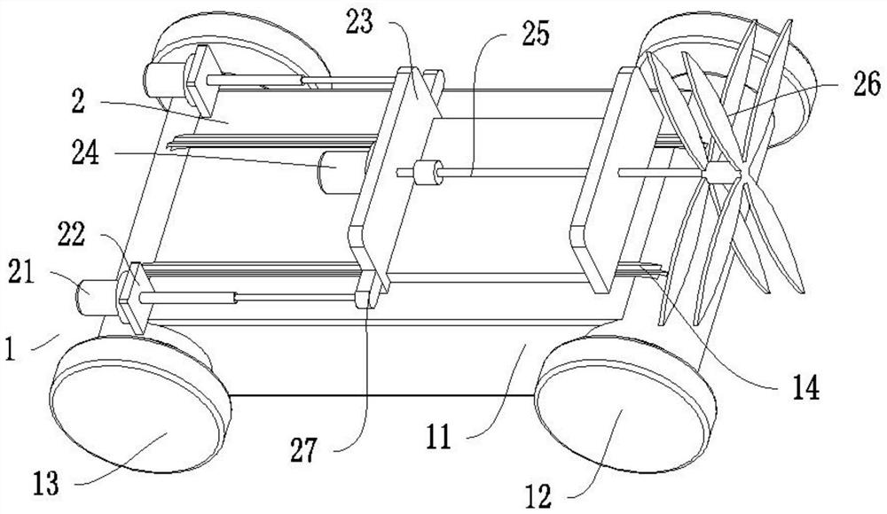
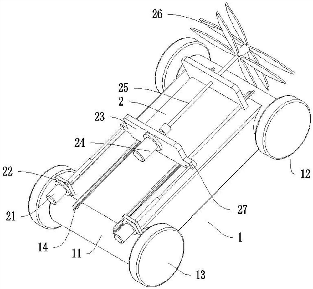
[0025] Such as figure 1 , 2 , 5, the drainage pipe desilting device includes a crawling mechanism 1 for transporting the device to the dredging position as a whole, the crawling mechanism 1 includes a vehicle frame 11, a first wheel 12, and 2 axles are installed on the vehicle frame 11 15. The axles 15 are connected to the frame 11 through bearings. One of the axles 15 is equipped with a first wheel 12 at the front and rear ends, and the other axle 15 is equipped with a second wheel 13 at the front and rear ends. The two axles 15 are symmetrically installed with 2 first bevel gears 16, the inner side of 2 first bevel gears 16 on one side are equipped with second bevel gears 17, the second bevel gears 17 are installed on the two ends of the first rotating shaft 18, the first rotating shaft 18 second bevel The gear 17 is connected by a key, and the second spur gear 111 is installed between the two second bevel gears 17 on the first rotating shaft 18. The second spur gear 111 is...

Embodiment 2

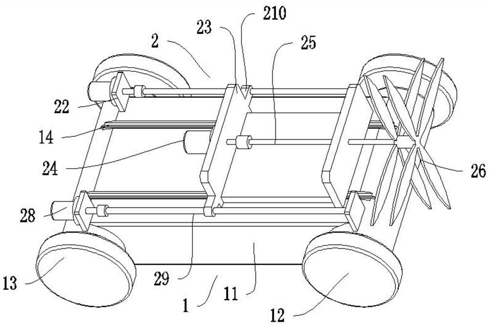
[0028] Such as image 3 , 4 , 5, the drainage pipe desilting device includes a crawling mechanism 1 for transporting the device to the dredging position as a whole, the crawling mechanism 1 includes a vehicle frame 11, a first wheel 12, and 2 axles are installed on the vehicle frame 11 15. The axles 15 are connected to the frame 11 through bearings. One of the axles 15 is equipped with a first wheel 12 at the front and rear ends, and the other axle 15 is equipped with a second wheel 13 at the front and rear ends. The two axles 15 are symmetrically installed with 2 first bevel gears 16, the inner side of 2 first bevel gears 16 on one side are equipped with second bevel gears 17, the second bevel gears 17 are installed on the two ends of the first rotating shaft 18, the first rotating shaft 18 second bevel The gear 17 is connected by a key, and the second spur gear 111 is installed between the two second bevel gears 17 on the first rotating shaft 18. The second spur gear 111 is...


PUM


Abstract

The invention discloses a drainage pipeline desilting device. The drainage pipeline desilting device comprises a crawling mechanism used for conveying the whole device to a desilting position, the crawling mechanism comprises a frame and first wheels, two wheel shafts are installed on the frame, the wheel shafts are connected with the frame through bearings, and the first wheels are installed at the front end and the rear end of one wheel shaft. A second motor runs to drive a second rotating shaft to rotate, then crushing blades at the ends rotate to crush blockages, the crushed blockages are washed in a drainage pipe under the action of water flow, the crushed blockages are drained away along with the water flow, and therefore the desilting purpose is achieved; and the crushing blades can perform regular reciprocating motion, and the crushing blades are in better contact with the blockages, so that the crushing efficiency and quality are improved.

Description

technical field [0001] The invention relates to the technical field of desilting devices, in particular to a desilting device for drainage pipes. Background technique [0002] Drainage pipes are used to transport domestic sewage or industrial wastewater. However, due to the long-term conveyance of the drainage pipes, the accumulation of some dirt causes the blockage of the pipes. Aiming at this situation, a pipe dredging device came into being. However, the existing municipal water supply and drainage The pipe dredging equipment has the following defects: the inside of the drainage pipe cannot be stirred, the dirt cannot be broken, the dredging effect and efficiency are low, and the practicability is poor. Contents of the invention [0003] The object of the present invention is to provide a drainage pipe dredging device in order to solve the above problems. [0004] The present invention achieves the above object through the following technical solutions: [0005] The d...

Claims


Application Information

Patent Timeline
Patent Type & Authority Applications(China)
IPC IPC(8): E03F7/10E03F9/00B02C18/00B02C18/14B02C21/02
Inventor 徐国平
Owner 长兴骋旭市政道路设施有限公司
Why Eureka
Eureka Blog
Learn More