Eureka AIR delivers breakthrough ideas for toughest innovation challenges, trusted by R&D personnel around the world.

Mine sump dredging device

A technology of dredging device and water tank, which is applied in the direction of safety device, drainage, mixer with rotating stirring device, etc., can solve the problems of difficult drainage, complicated equipment structure, high labor intensity, etc., and reduce the labor intensity of workers and equipment The structure is simple and the effect of improving work efficiency

Pending Publication Date: 2020-11-03
山西中科智能控制技术研究院有限公司
View PDF0 Cites 0 Cited by
  • Summary
  • Abstract
  • Description
  • Claims
  • Application Information

AI Technical Summary

Problems solved by technology

[0002] The water tank is an indispensable part of the mine drainage system. It has two main functions: one is to store water, and the other is to precipitate. The sediment in the tank needs to be dug out in time, otherwise the effective volume of the water tank will be reduced. When encountering a sudden water gushing, the water in the tank will overflow and cause the risk of flooding the parking lot at the bottom of the well; Blocking the suction faucet makes drainage difficult or impossible. Traditional manual dredging workers have high labor intensity, slow progress and low efficiency. Existing mechanical dredging uses special digging machinery to load the sludge into mine trucks and transport it out of the water tank. Although it can reduce the labor intensity of workers, the structure of the equipment is complicated, the cleaning effect is poor, and it is difficult for vehicles to walk in the water tank

Method used


Image

  • Mine sump dredging device
  • Mine sump dredging device
  • Mine sump dredging device

Examples


Embodiment Construction

[0017] The following will clearly and completely describe the technical solutions in the embodiments of the present invention with reference to the accompanying drawings in the embodiments of the present invention. Obviously, the described embodiments are only some, not all, embodiments of the present invention. Based on the embodiments of the present invention, all other embodiments obtained by persons of ordinary skill in the art without making creative efforts belong to the protection scope of the present invention.

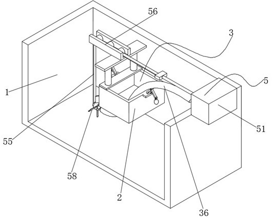
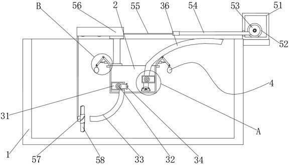
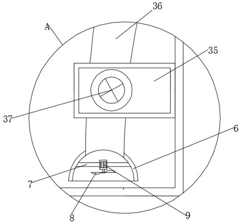
[0018] see Figure 1-4 , the present invention provides the following technical solutions: a mine water tank dredging device, including a water tank body 1, a sewage tank 2, a sewage assembly 3, a floating assembly 4, a traction assembly 5, a protective cover 6, a mounting frame 7, a fan blade 8 and a waterproof Motor 9, sewage tank 2 is installed on the inside of water tank body 1, and the inside of sewage tank 2 is provided with blowdown assembly 3; Sewage a...


PUM


Abstract

The invention discloses a mine sump dredging device which comprises a sump body, a sewage tank, a sewage discharging assembly, a floating assembly, a traction assembly, a protective cover, a mountingframe, fan blades and a waterproof motor, the sewage tank is mounted in the sump body, a first mounting box is welded to the inner wall of one side of the sewage tank, and a slurry pump is mounted andfixed to the inner wall of the bottom end of the first mounting box; and a water inlet pipe is connected and fixed to the position, corresponding to the slurry pump, in the sewage tank and fixedly connected with the slurry pump, a water inlet valve is mounted on the outer wall of one end of a water outlet of the water inlet pipe, a second mounting box is welded to the inner wall of the other sideof the sewage tank, and a sewage discharging pump is mounted and fixed to the inner wall of the bottom end of the second mounting box. The working efficiency is improved, compared with traditional manual mechanical dredging, the working efficiency is greatly improved, the labor intensity of workers is greatly relieved, the progress is faster, the working efficiency is higher, the equipment structure is simple, the clearing effect is better, and a vehicle can walk in the sump more easily.

Description

technical field [0001] The invention belongs to the technical field of mine water tank dredging, in particular to a mine water tank dredging device. Background technique [0002] The water tank is an indispensable part of the mine drainage system. It has two main functions: one is to store water, and the other is to precipitate. The sediment in the tank needs to be dug out in time, otherwise the effective volume of the water tank will be reduced. When encountering a sudden water gushing, the water in the tank will overflow and cause the risk of flooding the parking lot at the bottom of the well; Blocking the suction faucet makes drainage difficult or impossible. The traditional manual dredging workers have high labor intensity, slow progress and low efficiency. The existing mechanical dredging uses special digging machinery to load the sludge into the mine truck and transport it out of the water tank. Although the labor intensity of the workers can be reduced, the structure...

Claims


Application Information

Patent Timeline
IPC IPC(8): E21F16/00B01F7/04E02F5/28E02F3/88E02F3/90
CPCE21F16/00E02F5/28E02F3/88E02F3/90B01F27/70
Inventor 付国军李海平翟德华梁耀林方关民张亚锋
Owner 山西中科智能控制技术研究院有限公司
Why Eureka
Eureka Blog
Learn More