Adiabatic internal combustion engine combustion system based on adiabatic combustion chamber and Miller cycle

A Miller cycle, combustion system technology, applied in combustion engines, internal combustion piston engines, mechanical equipment, etc., can solve the problems of easy peeling off of thermal insulation coating, low thermal efficiency, deflagration, etc., to improve effective thermal efficiency, improve thermal efficiency, guarantee The effect of abrasion resistance

Active Publication Date: 2021-06-15
HUAZHONG UNIV OF SCI & TECH
View PDF31 Cites 2 Cited by
  • Summary
  • Abstract
  • Description
  • Claims
  • Application Information

AI Technical Summary

Problems solved by technology

Specifically, through the design of the thermal insulation coating and the Miller cycle in the thermal insulation cylinder, the overall thermal efficiency of the traditional thermal insulation internal combustion engine is not high, the thermal insulation coating is easy to fall off, and the knocking and deflagration caused by the high wall temperature of the thermal insulation cylinder are solved.

Method used


Image

  • Adiabatic internal combustion engine combustion system based on adiabatic combustion chamber and Miller cycle
  • Adiabatic internal combustion engine combustion system based on adiabatic combustion chamber and Miller cycle
  • Adiabatic internal combustion engine combustion system based on adiabatic combustion chamber and Miller cycle

Examples


Embodiment 1

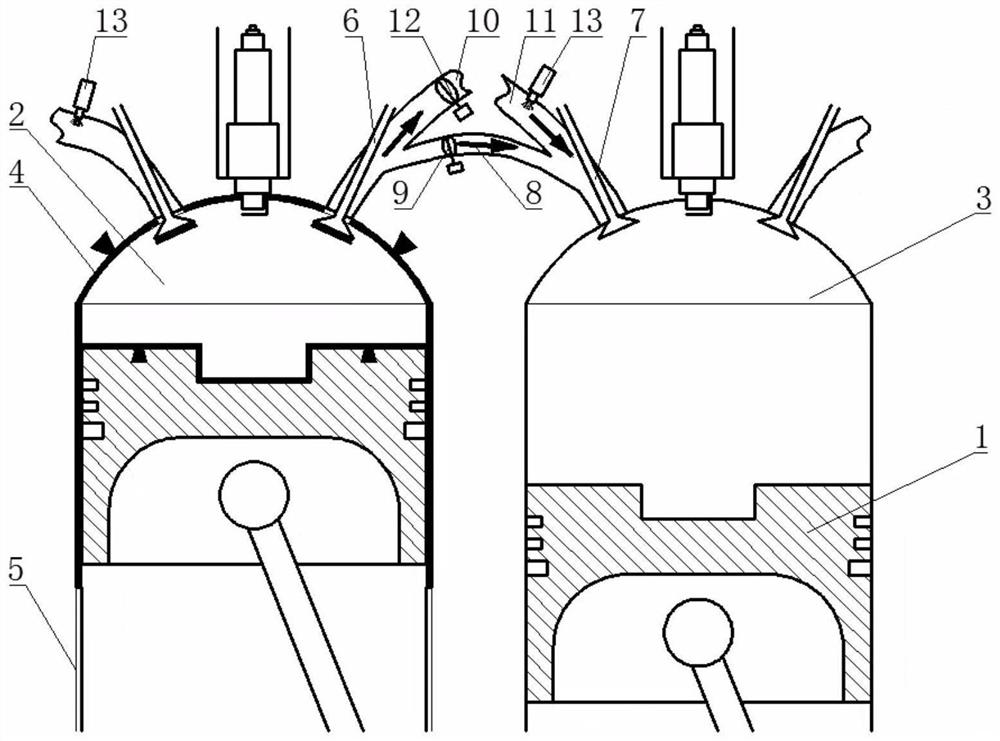
[0049] Taking a 4-cylinder 4-stroke gasoline engine as an example, it is assumed that the firing sequence of the engine is the commonly used 1-3-4-2, but the present invention is not limited to this case. Among them, 1-cylinder and 4-cylinder are set as adiabatic combustion chamber 2, and 2-cylinder and 3-cylinder are set as common combustion chamber 3. The working process of the engine is: intake process - compression process - work process - exhaust process. Since the firing sequence of each cylinder is commonly used 1-3-4-2, that is, 2-1-3-4, when the 1-cylinder piston 1 is in the intake stroke, the 2-cylinder piston 1 is in the compression stroke. Next, a dual-cylinder system composed of 1-2 cylinders is taken as an example to introduce the specific implementation of the present invention.

[0050] Such as figure 1 As shown, the exhaust passage of the adiabatic combustion chamber 2 is divided into an exhaust air passage 10 and a heat dissipation air passage 8 . Common c...


PUM


Abstract

The invention belongs to the related technical field of internal combustion engines, and particularly discloses an adiabatic internal combustion engine combustion system based on an adiabatic combustion chamber and a Miller cycle. According to the system, through combination of an adiabatic cylinder and the Miller cycle, the reliable operation of the internal combustion engine is ensured, and the overall heat efficiency of the internal combustion engine is improved. The system comprises the adiabatic cylinder and a common cylinder, the structure of the adiabatic cylinder is the same as that of the common cylinder, and the inner surface of a combustion chamber of the common cylinder is coated with a heat insulation coating used for reducing heat dissipation loss in the combustion chamber; A heat dissipation air channel is arranged between an exhaust channel of the adiabatic cylinder and an air inlet channel of the common cylinder, and used for connecting the adiabatic cylinder with the common cylinder and introducing excess air of the adiabatic cylinder into a common combustion chamber through secondary scavenging of an exhaust valve under the large-load working condition, and the abnormal combustion trend of the adiabatic cylinder is reduced; and the charging coefficient of the common combustion chamber is increased. The heat efficiency of the internal combustion engine is improved, and the problems that the insulating coating is prone to falling off, and the cylinder inner wall temperature is too high are solved.

Description

technical field [0001] The invention belongs to the technical field related to internal combustion engines, and more specifically relates to an adiabatic internal combustion engine combustion system based on an adiabatic combustion chamber and a Miller cycle. Background technique [0002] Due to its high speed, simple structure, light weight, and stable operation, internal combustion engines are widely used in various fields such as automobiles, ships, and construction machinery. However, internal combustion engines have different forms of energy losses, such as cooling losses, exhaust losses, etc., which reduce their thermal efficiency. With the development of the internal combustion engine industry, the thermal efficiency of the internal combustion engine has become a key bottleneck restricting the development of the internal combustion engine industry, and further improving the thermal efficiency of the internal combustion engine has become a major demand for the internal...

Claims


Application Information

Patent Timeline
Patent Type & Authority Applications(China)
IPC IPC(8): F02B23/08F02B25/00F02B25/26F02B75/02F02F1/24F02F3/14F02F3/26
CPCF02B23/08F02B25/00F02B75/02F02B25/26F02F1/24F02F3/14F02F3/26F02B2275/32F02B2075/027Y02T10/12
Inventor 王兆文曹俊辉袁波吴慧珉向林成晓北
Owner HUAZHONG UNIV OF SCI & TECH
Why Eureka
Try Eureka