Wind turbine and its transmission

A technology for wind turbines and transmission devices, which is applied to wind turbines, wind energy power generation, engines, etc., can solve the problems of high after-sales risk, high overall cost, difficult disassembly and maintenance, etc. The effect of reducing operational risk

Active Publication Date: 2022-07-01
SHANGHAI ELECTRIC WIND POWER GRP CO LTD
View PDF0 Cites 1 Cited by
  • Summary
  • Abstract
  • Description
  • Claims
  • Application Information

AI Technical Summary

Problems solved by technology

The transmission system of ordinary compact semi-direct drive units is mainly composed of low-speed shafting, couplings, medium-speed gearboxes and medium-speed permanent magnet motors. The gearbox of ordinary compact semi-direct drive units can save about 1 / 5 of the cost, but the medium-speed permanent magnet generator increases the cost by about 2 / 5 compared with the doubly-fed and squirrel-cage generator, and the cost of the coupling increases by about 3-4 times, so the overall cost is relatively high. There is no obvious advantage for the feeder model and the high-speed squirrel-cage model
The transmission system of the ultra-compact semi-direct drive unit is mainly composed of a medium-speed gearbox and a medium-speed permanent magnet, eliminating the need for low-speed shafting and couplings, highly integrating the main shaft bearing, gearbox and generator, and eliminating the need for a transmission system About 2 / 5 of the number of structural parts, the cost of this transmission system technology route has certain advantages in cost compared with direct drive and high-speed gearboxes, but this route is difficult to achieve disassembly maintenance, once a functional failure occurs, the tower needs to be removed as a whole Maintenance, after-sales risk is high

Method used


Image

  • Wind turbine and its transmission
  • Wind turbine and its transmission

Examples


Embodiment Construction

[0050] Exemplary embodiments will be described in detail herein, examples of which are illustrated in the accompanying drawings. Where the following description refers to the drawings, the same numerals in different drawings refer to the same or similar elements unless otherwise indicated. The implementations described in the illustrative examples below are not intended to represent all implementations consistent with the present invention. Rather, they are merely examples of apparatus and methods consistent with some aspects of the invention as recited in the appended claims.

[0051] The terminology used in the present invention is for the purpose of describing particular embodiments only and is not intended to limit the present invention. As used in this specification and the appended claims, the singular forms "a," "the," and "the" are intended to include the plural forms as well, unless the context clearly dictates otherwise. It will also be understood that the term "an...


PUM


Abstract

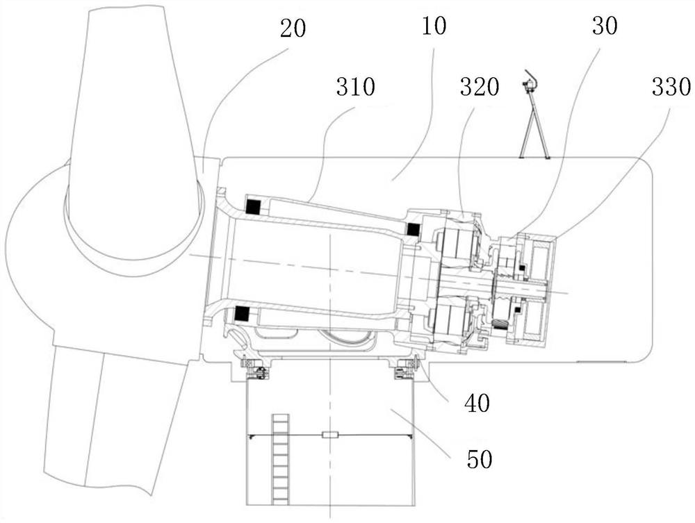
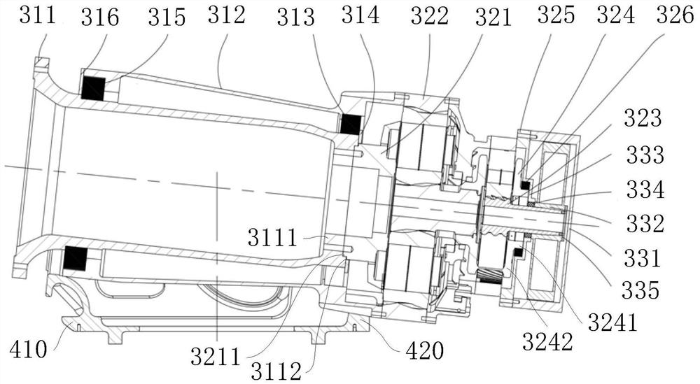
The invention provides a wind turbine generator set and its transmission device. The transmission device includes a transmission shaft system, a gear box and a generator. The front end of the transmission shaft system is connected to the hub of the wind wheel of the wind turbine generator set, and the input end of the gear box is connected to the transmission shaft. The rear end of the transmission system is connected, and the output end of the gear box is connected with the input end of the generator; a bearing is shared between the transmission shaft system and the gear box and / or a bearing is shared between the gear box and the generator. The present invention implements a semi-integrated design between the transmission shaft and the gearbox and / or between the gearbox and the generator, that is, the transmission shaft and the gearbox share a bearing, and / or the gearbox and the generator A single bearing is shared between them to achieve a compact structure layout, effectively making up for the shortcomings of the complex structure, low reliability and high cost of the current wind turbine; at the same time, it reduces the size of each component of the unit, reduces manufacturing and transportation costs, and realizes detachable maintenance. Reduce operational risk.

Description

technical field [0001] The invention relates to the field of wind generator sets, in particular to a wind generator set and a transmission device thereof. Background technique [0002] At present, there are three technical routes for the transmission system of wind turbines: 1), high-speed gearbox plus double-fed motor / squirrel cage motor / high-speed permanent magnet motor, often referred to as high-speed double-fed type / squirrel cage asynchronous type / high-speed Permanent magnet synchronous model (or high-speed gearbox model); 2), low-speed permanent magnet generator / low-speed electric excitation generator without gearbox, often called direct drive permanent magnet synchronous model (or direct drive model) / direct drive excitation synchronous model; 3), medium-speed gearbox plus medium-speed double-fed motor / medium-speed permanent magnet motor, often referred to as medium-speed double-fed model / medium-speed permanent magnet synchronous model (or semi-direct drive model...

Claims


Application Information

Patent Timeline
Patent Type & Authority Patents(China)
IPC IPC(8): F03D15/00F03D80/70F03D80/00
CPCF03D15/00F03D80/70F03D80/00Y02E10/72Y02P70/50
Inventor 赵大文李红梅杨飞孙振军
Owner SHANGHAI ELECTRIC WIND POWER GRP CO LTD
Why Eureka
Try Eureka