Battery module terminal voltage regulating circuit and device
A battery module and regulation circuit technology, applied in the field of power supply, can solve problems such as inability to meet high current and voltage control accuracy
Pending Publication Date: 2021-06-15
浙江大学绍兴微电子研究中心 +2
0 Cites 0 Cited by
AI-Extracted Technical Summary
Problems solved by technology
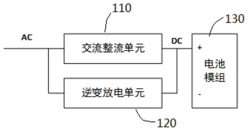
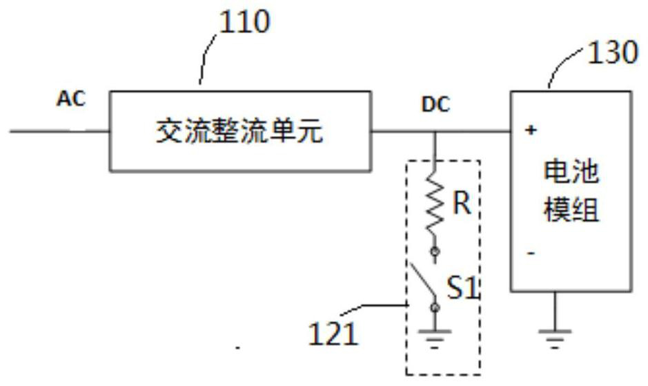
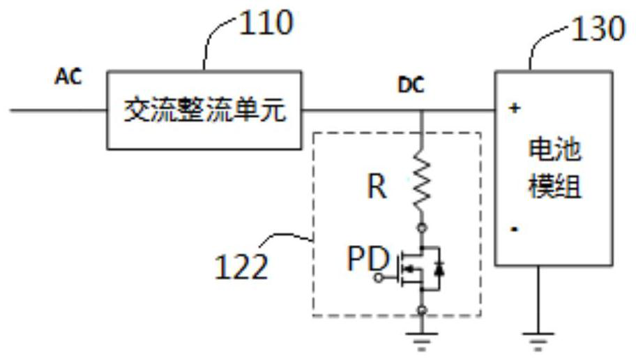
However, if it is necessary to meet the requirements of a wide voltage range and the constant discharge current can be set arbitrarily, only the DC/DC converter discharge unit 124 can be used as the discharge unit. For details, please refer to Figure 5 Shown is a schemat...
Abstract
The invention relates to a battery module terminal voltage regulating circuit, which relates to the field of power supplies. The battery module terminal voltage regulating circuit comprises an alternating current rectifying unit of which the input end receives alternating current and the output end is connected with a direct current bus and is used for converting the alternating current into direct current bus voltage; a battery charging and discharging unit, wherein the first end of the battery charging and discharging unit is connected with the direct-current bus, the second end of the battery charging and discharging unit is connected with a battery module, and the battery charging and discharging unit is used for converting the direct-current bus voltage of the first end into direct-current voltage of the second end to charge the battery module, or converting the direct-current voltage of the second end into the direct-current bus voltage of the first end; and an energy-consuming discharge unit connected with the direct-current bus, wherein the battery module discharges through the battery charging and discharging unit and the energy-consuming discharge unit, so that the design is simple, and standardization can be realized.
Application Domain
Circuit monitoring/indicationDifferent batteries charging +2
Technology Topic
DC - Direct currentElectrical battery +9
Image
Examples
- Experimental program(1)
Example Embodiment
[0027] The technical solutions in the present invention will be described in conneffled and complete, and embodiments, below, will be described below, as will be described in connection with the accompanying drawings. Based on the embodiments of the present invention, all other embodiments obtained by those of ordinary skill in the art without making creative labor are the scope of the present invention.
[0028]It should be understood that the invention can be implemented in different forms without interpretation as limiting herein. Conversely, these embodiments will be made entirely and complete, and the scope of the invention is fully transmitted to those skilled in the art. In the drawings, for clarity, the size of the layer and the region and the relative dimension may be exaggerated, the same elements are indicated by the same reference numerals. It should be understood that when the element or layer is referred to as "" "," adjacent "," connect to "or" coupled to "other elements or layers, it can be directly on other components or layers, with Adjacent adjacent, coupled or coupled to other elements or layers, or may exist in an intercept element or layer. Conversely, when the element is called "directly in ...", "directly adjacent", "directly coupled" or "directly coupled to" other elements or layers, there is no interval element or layer. It should be understood that although various elements, components, regions, layers, and / or portions can be used, such elements, components, regions, layers, and / or moieties should not be limited by these terms. These terms are only used to distinguish between one element, component, zone, layer or portion with another element, component, region, layer or portion. Accordingly, the first element, component, region, layer, or portion discussed below is not departed from the teachings of the present invention, can be expressed as the second element, component, region, layer or portion.
[0029] Spatial relationship terms such as "under ...", "in ...", "below", "under ...", "above", "above", etc., here can be used for convenience description Thereby the relationship between one element or feature shown in the figure and other elements or features shown. It should be understood that in addition to the orientation shown in the figures, the spatial relationships also include different orientations of the devices in use and operations. For example, if the device in the drawings is flip, then "under other components" or "lower" or "under" or "lower" element or feature will be oriented to be in other components or feature "on". Therefore, exemplary terms "in ..." and "under ..." may include upper and lower orientations. The device can additionally orientation (rotate 90 degrees or other orientation) and the spatial descriptor used herein is correspondingly explained.
[0030] The object of the terms used herein is to describe specific embodiments and are not limited as the invention. When used here, "a" "one", "one", and the "/ this" in the singular form are also intended to include plural, unless the context clearly indicates another manner. It should also be understood that terms "composition" and / or "include", when used in this specification, the features, integers, steps, operations, components, and / or components are present, but do not exclude one or more other Features, integers, steps, operations, components, components, and / or group presence or addition. The terms "and / or" include any and all combinations of the related items when used herein.
[0031] The technical solutions in the present invention will be described in conneffled and complete, and embodiments, below, will be described below, as will be described in connection with the accompanying drawings. Based on the embodiments of the present invention, all other embodiments obtained by those of ordinary skill in the art without making creative labor are the scope of the present invention.
[0032] In an embodiment of the invention, it is to provide a battery module end voltage regulating circuit, see Figure 6 The battery module end voltage regulating circuit shown in the first embodiment of the present invention includes: AC rectifier unit 210, the input terminal receives AC (AC IN), the output is connected to the DC bus (DC BUS) for The alternating current is converted to a DC bus voltage VBus; the battery charge and discharge unit 250, the first end is connected to the DC bus (DC BUS), and the second end is connected to the battery module 230 for the DC of the first end. The bus voltage Vbus transforms the DC voltage (DC OUT) of the second end to charge the battery module 230, or convert the DC voltage (DC OUT) of the second end into the DC voltage of the first end. The VBUS; the energy consumption discharge unit 220 is connected to the DC bus (DC BUS), and the battery module 230 is discharged through the battery charge and discharge unit 250 and the energy discharge unit 220.
[0033] As such, the charge and discharge constant current constant voltage of the battery module is determined by the battery charge and discharge unit 250, and since the DC bus voltage Vbus on the DC bus is substantially constant, or only in a minimum range (such as 3V ), The energy consumption discharge unit 220 only assumes the function of the required discharge power adjustment, without having to restrict the voltage level of different battery modules, and is simple and standardized.
[0034] In one embodiment, the AC rectifier unit 210 can be any AC / DC converter, as long as the alternating current to direct current transformation, the present application does not limit its specific structure.
[0035] In one embodiment, the battery charge and discharge unit 250 is a two-way DC / DC converter for performing mutual conversion between DC Paste VBus and DC voltage (DC OUT), which can be a two-way full bridge converter, buck -boost converter or the like to achieve a converter for DC-current bidirectional transformation.
[0036] See more, see Figure 7 , Figure 7 A battery module end voltage adjustment circuit is a battery module end voltage regulating circuit for another embodiment of the present invention. Compared to Figure 6 The battery module terminal voltage regulating circuit, Figure 7 The energy consumption discharge unit 220 shown in the battery module terminal voltage regulating circuit includes: at least one discharge branch 222 including the resistor R and the switch S series and at least one DC / DC converter 221, and the discharge branch The first end of the road 222 and the first end of the DC / DC converter 221 are connected to the DC bus (DC BUS), the discharge branch 222, and the second end of the DC / DC converter. Both ground, and form a parallel and discharged structure. The control causes the switch in the discharge branch 222 to conduct or turn off, so that the DC / DC converter 221 operates with the discharge branch 222 to discharge the battery module 230. During the discharge process, the DC / DC converter 221 operates to keep the DC bus voltage Vbus a constant value, or only in a minimum range (such as 3V), which is generally higher than the AC rectifier unit. The constant voltage output value of 210. The DC / DC converter 221 cooperates with the discharge branch 222 to achieve linear adjustment discharge power over the entire system. Also, since the DC bus voltage Vbus is substantially constant, the resistance resistance value in the discharge branch 222 can be simply determined according to its own power configuration, and a large quantity of manufacturing without the difference in voltage level of different battery modules.
[0037] In an embodiment, the specific structure of the DC / DC converter 221 is not limited as long as the DC electricity to DC electrical transformation can be realized.
[0038] The present invention also provides a battery module end voltage regulating device. Specifically, see Figure 8 The battery module end voltage regulating apparatus shown in the embodiment shown in the present invention is schematically showing Figure 7 The battery module terminal voltage regulating circuit, further comprising: control and sampling unit 260, control and sampling unit 260 connected each discharge branch 222 and DC / DC converter 221 in the energy consumption discharge unit 220, AC rectification The unit 210 and the battery charge and discharge unit 250 are used to output a control signal to the switch S and the switch in the DC / DC converter 221, the switch and the battery charge and discharge unit 250 in the AC rectifier unit 210. The inner switches, while controlling the battery module end voltage regulating circuit to operate in the charging mode or discharge mode, the switching of the switch and the switch within the battery charge and discharge unit 250 in the charging mode operates to charge the battery module 230. In the discharge mode, the switch S in the battery charge and discharge unit 250 is discharged to the battery module 230 in the switch S and the switch in the DC / DC converter 221 in each discharge branch 222.
[0039] In one embodiment, if Figure 8 The control and sampling unit 260 also connect the battery module 230 for sampling the end voltage of the battery module 230, and when the battery module 230 is lower than the charging threshold, the control and sampling unit 260 controls the battery module terminal. The voltage regulating circuit operates in the charging mode, when the battery module 230 is higher than the discharge threshold, the control and sampling unit 260 controls the battery module terminal voltage regulating circuit to operate in the discharge mode and make the battery module 230 through the battery charge and discharge unit. 250 and the energy consumption discharge unit 220 discharges.
[0040] The power grade of the discharge branch 222 and the DC / DC converter 221 can use different configuration methods to discharge the number of discharge branch 222 as an example. In an embodiment, discharge branch 222 and DC / DC variable flow The average distribution of the device 221, that is, the design power of the discharge branch 222 and the DC / DC converter 221, where PMax is the system design power, at this time, the design power of the DC / DC converter 221 is only 25% of the system power, can reduce the design difficulty and cost of the DC / DC converter 221, and due to the substantially constant VBus on the DC bus voltage on the DC bus, or only in a minimum range (such as 3V) The discharge branch 222 only assumes that the function of the desired discharge power is adjusted, and there is no need to pay different voltage levels of different battery modules, so the design is simple and standardized. Of course, the "average" "average" is not absolute "average", that is, the design power of the discharge branch 222 and the DC / DC converter 221 is not completely equal, and it can have a deviation within 10%, which is better. Deviation within 5%.
[0041] In an embodiment, the design power of the DC / DC converter 221 is designed to be between 103% and 105% of the design power of the design power of the discharge branch 222 to reduce the fluctuation of the discharge power switching. In addition, the discharge power is continuously adjustable and the impact on the load end is reduced.
[0042] In another embodiment, it is also equivalent to discharge branch 222 and DC / DC converter 221, such as P1: P2: P3: PDC / DC = 1: 2: 4: 1, p1, p2, p3 The PDC / DC is the design power of the first discharge branch, the second discharge branch, the third discharge branch and DC / DC converter 221, and the design can be further further designed by DC / DC converter 221. Decrease 12.5% of the system power, and further reduce design difficulty and system cost, and the discharge branch 222 is only responsible for the functional adjustment of the desired discharge power, without ingressing the voltage level of different battery modules, therefore Simple design, and standardized.
[0043] In the discharge mode, the discharge branch 222 cooperates with the DC / DC converter 221 to discharge the battery module 230. The specific working principle is as follows:
[0044] In an embodiment, the design power of the DC / DC converter 221 can leave a margin of no more than 10%, so that the DC / DC will not operate in a load state of 90% or more or 10% when power switching. Increase its stability. In order to reach the design power of the DC / DC converter 221, no more than 10% of the margin, each discharge branch 222 needs to switch, in general, as the discharge power is reduced, DC / DC converter 221 The output power will be reduced when the switching critical point (typically set to 10% of the DC / DC converter 221 design power), and the discharge power undertakes the discharge branch 222 is reduced. With this type, until the battery module 230 reaches the discharge threshold. The number of discharge branch 222 is 3, and the system design power is 3000W as an example. In the first embodiment, the first discharge branch P 1 , Second discharge branch P 2 And the third discharge branch P 3 The design power is 750W, and the DC / DC converter 221 has a design power of 800W. The DC bus voltage Vbus on the DC bus is 48V, the first discharge branch P 1 , Second discharge branch P 2 And the third discharge branch P 3The internal resistance resistance value is approximately 3 ohms, and the DC / DC converter 221 can also use the resistance load and the load resistance is about 2.9 ohms. The control signal control output by the initial discharge, control and sampling unit 260 causes the first discharge branch P 1 , Second discharge branch P 2 And the third discharge branch P 3 Built-in switches are turned on, specific, can be found Figure 9 Shown Figure 8 The control principle of the control method shown in the battery module end voltage regulator device. Before T1, the first discharge branch P 1 , Second discharge branch P 2 And the third discharge branch P 3 The built-in switch is turned on, and the end voltage of the battery module 230 is gradually lowered, and the discharge power is lowered, and the DC / DC converter 221 gradually reduces the discharge power, to T1, when DC / DC is gradually reduced by adjusting the duty cycle. When the discharge power of the converter 221 is reduced to 10% or less, the first discharge branch P 1 Internal switch, only second discharge branch P 2 And the third discharge branch P 3 The built-in switch is turned on, and at this time, the discharge power of the DC / DC converter 221 will be automatically lifted to keep the DC bus voltage Vbus on the DC bus. Up to T2, the DC / DC converter 221 discharges the second discharge branch P in time when the discharge power is reduced to 10% below. 2 Inside the switch, only the third discharge branch P 3 The built-in switch is turned on, and at this time, the discharge power of the DC / DC converter 221 will be automatically lifted to keep the DC bus voltage Vbus on the DC bus. At T3, the DC / DC converter 221 discharges the third discharge branch P in when the discharge power is reduced to 10%. 3 In the inner switch, only the DC / DC converter 221 is discharged, then, at this time, the discharge power of the DC / DC converter 221 will be automatically lifted to maintain the DC bus voltage Vbus on the DC bus line, and with the discharge power Reduce, the DC / DC converter 221 adjusts the duty ratio until the discharge is completed. As such, the DC bus voltage Vbus on the DC bus is substantially constant, or only in a minimum range (such as 3V), the energy consumption discharge unit 220 is only responsible for the function of adjusting the required discharge power, and There is no need to pay different voltage levels of different battery modules, so it is simple and standardized, without subject to the difference in voltage levels of different battery modules. That is, the control and sampling unit 260 controls the number of discharge branch 222 on which the energy-consuming discharge cell 220 is connected is sequentially reduced until only DC / DC converter 221 operates separately to the discharge end. The DC bus voltage Vbus is avoided from the DC bus voltage. In the second embodiment, the design makes the first discharge branch P 1 , Second discharge branch P 2 And the third discharge branch P 3 The design power is 375W, 750W and 1500W, respectively, the first discharge branch P 1 , Second discharge branch P 2 And the third discharge branch P 3 The internal resistance resistance value is approximately 6 ohms, 3 ohm and 1.5 ohms, DC / DC converter 221 design power is 400W, and DC / DC converter 221 can also use the resistance load, the load resistance is about 5.9 ohms. The DC bus voltage Vbus on the DC bus is 48V. The control signal control output by the initial discharge, control and sampling unit 260 causes the first discharge branch P 1 , Second discharge branch P 2 And the third discharge branch P 3 Built-in switches are turned on, specific, can be found Figure 10 Shown Figure 8 The control principle of the control method of the battery module end voltage adjustment device is shown. Before T1, the first discharge branch P 1 , Second discharge branch P 2 And the third discharge branch P 3 The built-in switch is turned on, and the end voltage of the battery module 230 is gradually lowered, and the discharge power is lowered, and the DC / DC converter 221 gradually reduces the discharge power, to T1, when DC / DC is gradually reduced by adjusting the duty cycle. When the discharge power of the converter 221 is reduced to 10% or less, the first discharge branch P 1 Internal switch, second discharge branch P 2 And the third discharge branch P 3 The built-in switch is turned on to discharge, then, at this time, the discharge power of the DC / DC converter 221 will be automatically lifted to maintain the DC bus voltage Vbus on the DC bus. At T2, when the DC / DC converter 221 discharge power is reduced to 10% or less, the second discharge branch P is turned off. 2 Internal switch, and simultaneously make the first discharge branch P 1 The inner switch is turned on, the first discharge branch P 1 And the third discharge branch P 3 At this time, at this time, the discharge power of the DC / DC converter 221 will be automatically lifted to keep the DC bus voltage Vbus on the DC bus. At T3, when the DC / DC converter 221 discharge power is reduced to 10% or less, the switch in the first discharge branch P1 is turned off, the third discharge branch P1 3 The built-in switch is turned on, and at this time, the discharge power of the DC / DC converter 221 will be automatically lifted to keep the DC bus voltage Vbus on the DC bus. At T4, when the DC / DC converter 221 discharge power is reduced to 10% or less, turn off the third discharge branch P 3 Internal switch, and simultaneously make the first discharge branch P 1 And second discharge branch P 2 The inner switch is turned on, the first discharge branch P 1 And second discharge branch P 2 At this time, at this time, the discharge power of the DC / DC converter 221 will be automatically lifted to keep the DC bus voltage Vbus on the DC bus. At T5, when the DC / DC converter 221 discharge power is reduced to 10% or less, the first discharge branch P is turned off. 1 Internal switch, second discharge branch P 2 At this time, at this time, the discharge power of the DC / DC converter 221 will be automatically lifted to keep the DC bus voltage Vbus on the DC bus. At T6, when the DC / DC converter 221 discharge power is reduced to 10% or less, the second discharge branch is turned off. 2 Internal switch, and simultaneously make the first discharge branch P 1 The inner switch is turned on, and the first discharge branch P1 is discharged. At this time, the discharge power of the DC / DC converter 221 will be automatically lifted to keep the DC bus voltage VBus on the DC bus. At T7, when the DC / DC converter 221 discharge power is reduced to 10% or less, the first discharge branch is turned off. 1 The inner switch, at this time, only the DC / DC converter 221 performs discharge, the discharge power of the DC / DC converter 221 will be automatically improved to keep the DC bus voltage Vbus on the DC bus line, and with the discharge power Reduce, the DC / DC converter 221 adjusts the duty ratio until the discharge is completed. As such, the DC bus voltage Vbus on the DC bus is substantially constant, or only in a minimum range (such as 3V), the energy consumption discharge unit 220 is only responsible for the function of adjusting the required discharge power, and There is no need to pay different voltage levels of different battery modules, so it is simple and standardized, without subject to the difference in voltage levels of different battery modules. That is, the control and sampling unit 260 controls the discharge branch 222 in the energy consumption discharge unit 220 to turn the discharge power achieved by all discharge branches into the discharge branch until only DC / DC converter 221 is operated separately. The discharge is over. The DC bus voltage Vbus is avoided from the DC bus voltage.
[0045] For the convenience of production, reduce the number of resistance resistance values, one of the design powers of one discharge branch is 1 / n of the design power of other discharge branches, where N is an integer of greater than 1. In the second embodiment described above, the first discharge branch P 1 Design power is the second discharge branch P 2 1/2, first discharge branch P 1 Design power is the third discharge branch P 2 1/4, the second discharge branch P 2 And the third discharge branch P 3 The resistance in the medium is made from the first discharge branch line P 1 The resistance is composed, such as the second discharge branch P 2 The resistance in the middle is from 2 groups of first discharge branch P 1 The resistance composition, the third discharge branch P 3 The resistance in 4 sets of first discharge branches P 1 The resistance is composed. That is, the interior of the discharge branch can also be standard modular, and mass production is performed.
[0046] for Figure 9 with Figure 10 The embodiment shown, the switches in the discharge branch are only turned on and off, i.e., the switches are turned off or turned on. Since the DC / DC converter 221 dynamic response can be lack of dynamic response Therefore, it is possible to cause transients of the DC bus voltage on the DC bus, if the transient high frequency fluctuation exceeds 5% DC bus voltage Vbus, it may be coupled to the battery module side by battery charge and discharge unit 250, short time affecting discharge Current acquisition accuracy and capacity calculation accuracy. See Figure 11 Shown Figure 8 A control waveform of another embodiment of the battery module end voltage regulating device is shown. In the first discharge branch P 1 When the switch is turned off, the DC / DC converter 221 dynamically responds to insufficient dynamic response, so the instantaneous reduction of the DC bus voltage VBus on the DC bus is reduced. If the transient high frequency fluctuation exceeds 5% DC bus voltage Vbus, The battery charge and discharge unit 250 may be coupled to the battery module side, short time affecting the discharge current collecting accuracy and capacity calculation accuracy. To avoid this, the switches in the discharge branch can be used as power devices, while the linear zone can be operated. In the process of turning off the discharge branch, the switch is controlled in the linear zone, and minimizes the transients of the DC bus voltage Vbus on the DC bus. See Figure 12 Shown Figure 8 The control principle of the control method of the battery module end voltage adjustment device is shown. At shutting down the first discharge branch P 1 During the process, control the first discharge branch P 1 The inner switch is in linear zone, then the working power of the DC / DC converter 221 is slowly changed, and the DC bus voltage on the DC bus line generates only minimal transient without affecting the control and sampling unit 260 pair discharge. The current collecting accuracy and capacity calculation accuracy, and ensures that the current control of the battery module terminal of the battery charge and discharge unit 250 satisfies the high precision requirements of the whole process.
[0047] It will be noted in that the above embodiments are intended to illustrate the technical solutions of the present invention, not limiting the invention, although the present invention will be described in detail, and those skilled in the art will understand: The technical scheme described in the foregoing embodiments can still be modified, or partially or all of the techniques is equivalent to alternative; and these modifications or replacements do not allow the present invention to take advantage of the present invention. range.
PUM


Description & Claims & Application Information
We can also present the details of the Description, Claims and Application information to help users get a comprehensive understanding of the technical details of the patent, such as background art, summary of invention, brief description of drawings, description of embodiments, and other original content. On the other hand, users can also determine the specific scope of protection of the technology through the list of claims; as well as understand the changes in the life cycle of the technology with the presentation of the patent timeline. Login to view more.