High-precision low-jitter delay pulse generator

A pulse generator and low jitter technology, applied in the field of sub-nanosecond delay pulse generation devices, can solve the problems of limited delay dynamic range, low pulse output jitter, and inability to obtain, and reduce system integration and cost. Effect

Active Publication Date: 2021-06-15
TIANJIN UNIV
View PDF4 Cites 4 Cited by
  • Summary
  • Abstract
  • Description
  • Claims
  • Application Information

AI Technical Summary

Problems solved by technology

[0003] The principle of counter method delay is to count the stable clock signal, and control the delay time by controlling the number of counts. This method is relatively easy to obtain a large dynamic range Delay, but the control of the sampling clock frequency, the delay resolution will not be very high, and the jitter of the output pulse is also affected by the sampling clock, resulting in the same size of the pulse output jitter as the delay resolution, and it is impossible to obtain a lower pulse output Jitter; the numerical control delay line method uses analog circuit technology to achieve precise control of pulse delay. This method converts the set delay information into a voltage value through D / A, and triggers the ramp circuit when the external trigger signal arrives. The comparator compares the voltage value of D / A with the voltage value of the ramp circuit, and outputs a delayed pulse when the two are equal
This method can obtain very high delay resolution, but the delay dynamic range is very limited

Method used


Image

  • High-precision low-jitter delay pulse generator
  • High-precision low-jitter delay pulse generator
  • High-precision low-jitter delay pulse generator

Examples


Embodiment Construction

[0017] The present invention will be described in further detail below in conjunction with the accompanying drawings and specific embodiments. It should be understood that the specific embodiments described here are only used to explain the present invention, not to limit the present invention.

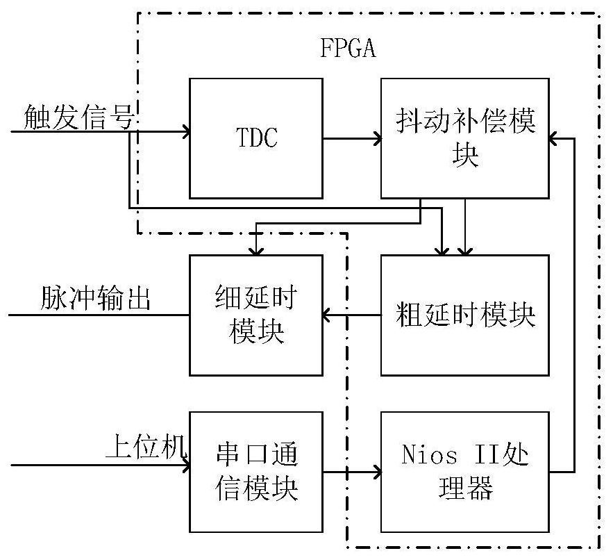
[0018] Such as figure 1 The high-precision low-jitter delay pulse generator shown is composed of TDC module, jitter compensation module, coarse delay module, Nios II processor module, serial port communication module, fine delay module and other parts, among which TDC module, jitter compensation, The coarse delay module and the Nios II module are all inside the same FPGA.

[0019] The external trigger signal enters the delay system through the trigger signal input interface, the trigger level is 3.3V LVTTL, and the input impedance is 50Ω.

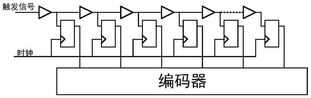
[0020] Such as figure 2 The structure diagram of the TDC module is shown. After the external trigger signal arrives, it will propagate along t...


PUM


Abstract

The invention discloses a high-precision low-jitter delay pulse generator which comprises the following steps: a time digital controller (TDC) module is used for measuring a time interval between an external trigger signal and a clock signal and is used for compensating jitter of pulse output; a jitter compensation module which processes time information measured by the TDC and delay information set by a user to obtain final delay information and compensates the final delay information to an output pulse; a coarse delay module which is used for performing coarse delay on the trigger signal and outputting the delayed signal to the fine delay chip; a serial port communication module which is used for sending delay information set by a user to an upper computer; and a Nios II soft core processor module which is used for processing the set information and sending the set information to the corresponding module. According to the invention, the problems of low precision of a counter and small delay range of a numerical control delay chip are solved by using a coarse-fine combined delay method, and the jitter of an output pulse is greatly reduced by using a TDC technology. Therefore, the whole system is high in integration degree, wherein the dtelay precision reaches 22 ps, and the pulse output jitter is 500 ps.

Description

technical field [0001] The invention relates to a timing synchronization device. In particular, a sub-nanosecond time-delayed pulse generator for time-of-flight mass spectrometers. Background technique [0002] The pulse delay generator is a timing control instrument, which can use a certain trigger signal as the zero point of time, and output a pulse signal with adjustable delay relative to the zero point of time, which is used to drive the work of other instruments, so as to realize the control of multiple The timing control of the instrument, the pulse delay generator plays a key role in high-speed framing cameras, radar systems, time-of-flight mass spectrometers and other equipment. The methods for realizing pulse delay include counter method and numerical control delay line method. [0003] The principle of the counter delay method is to count the stable clock signal, and control the delay time by controlling the number of counts. This method is relatively easy to obt...

Claims


Application Information

Patent Timeline
Patent Type & Authority Applications(China)
IPC IPC(8): H03K5/15
CPCH03K5/15
Inventor 马雷陈泽洋王笑晗
Owner TIANJIN UNIV
Why Eureka
Try Eureka