
Imaging device and method for thermoacoustic, photoacoustic, ultrasonic collinear excitation and reception

An imaging device, ultrasonic emission technology, applied in the direction of ultrasonic/sonic/infrasonic diagnosis, application, acoustic diagnosis, etc., can solve the problem of inability to achieve uniform thermoacoustic ultrasonic excitation and imaging, inability to detect non-protruding feature parts, and inability to respond to microwaves Absorption and other problems, to achieve the effect of ensuring the uniformity of the excitation area, large range, and flexible scenes

Active Publication Date: 2021-06-18
SOUTH CHINA NORMAL UNIVERSITY
View PDF7 Cites 3 Cited by
  • Summary
  • Abstract
  • Description
  • Claims
  • Application Information

AI Technical Summary

Problems solved by technology

But the above-mentioned patent still has some deficiencies: 1. The device adopts a horn antenna, which is bulky and inconvenient to move; The central detection area of ​​the ring detector is used for detection, and the parts without raised features are difficult to be placed in the central detection area of ​​the ring detector, so the device cannot detect some parts without raised features, such as the head and neck. and abdomen
3. Since the microwave thermoacoustic imaging device of the device uses a circular bell mouth to output microwaves, the area with uniform microwave field energy is small and its position is fixed. Uniform microwave excitation cannot be achieved for large-sized samples, resulting in images that cannot reflect reality microwave absorption
However, the existing thermoacoustic, photoacoustic, and ultrasonic three-mode systems are bulky or have a small imaging range, and cannot achieve uniform thermoacoustic, photoacoustic, and ultrasonic excitation and imaging.

Method used


Image

  • Imaging device and method for thermoacoustic, photoacoustic, ultrasonic collinear excitation and reception
  • Imaging device and method for thermoacoustic, photoacoustic, ultrasonic collinear excitation and reception
  • Imaging device and method for thermoacoustic, photoacoustic, ultrasonic collinear excitation and reception

Examples


Embodiment Construction

[0049] In order to enable those skilled in the art to better understand the solutions of the present application, the technical solutions in the embodiments of the present application will be clearly and completely described below in conjunction with the drawings in the embodiments of the present application. Apparently, the described embodiments are only some of the embodiments of this application, not all of them. Based on the embodiments in this application, all other embodiments obtained by those skilled in the art without making creative efforts belong to the scope of protection of this application.

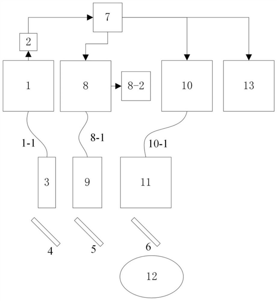
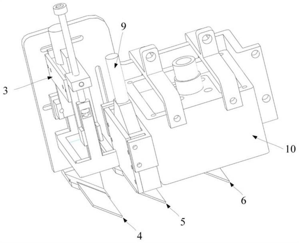
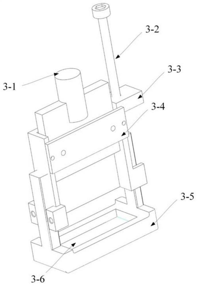
[0050] Such as figure 1 , figure 2 As shown, this embodiment is used for thermoacoustic, photoacoustic, ultrasonic collinear excitation and receiving imaging device, including pulse laser generation module 1, photoelectric detection module 2, linear light shaping module 3, mirror 4, light-transmitting mirror 5. Reflective acoustic mirror 6, pulse synchronization signal ge...


PUM


Abstract

The invention discloses an imaging device and method for thermoacoustic, photoacoustic and ultrasonic collinear excitation and reception. The imaging device comprises a pulse laser generation module, a photoelectric detection module, a linear light shaping module, a reflector, a light-transmitting reflector, a light-reflecting and sound-reflecting mirror, a pulse synchronization signal generation module, an ultrasonic emission / signal acquisition module, an image reconstruction module, an array ultrasonic transducer, a microwave generation module, a microwave antenna and a motor scanning module. According to the imaging device, a light field, a sound field and a microwave field coaxially and collinearly irradiate a surface of a sample, energy distribution of the microwave field, the light field and the sound field in the detection area is relatively uniform, and uniform and high-sensitivity thermoacoustic, photoacoustic and ultrasonic imaging at the same position of the detected sample can be realized. The integrated imaging device not only can be held by hand to obtain three-mode tomography in real time, but also can be driven by a scanning module to achieve rapid large-range three-dimensional imaging, and acquire more complete and comprehensive complementary information.

Description

technical field [0001] The invention belongs to the technical field of microwave thermoacoustic, photoacoustic and ultrasonic imaging technologies, and in particular relates to an imaging device and method for collinear excitation and reception of thermoacoustic, photoacoustic and ultrasonic. Background technique [0002] Multimodal imaging systems can provide more complementary information than single modality systems: microwave thermoacoustic imaging can provide information such as the dielectric constant in tissues; photoacoustic imaging can provide differences in light absorption coefficients in tissues; and ultrasonic imaging Can provide information on differences in acoustic impedance in tissue. These parameters play an important role in improving the diagnostic ability of early-stage tumors and have attracted extensive research. The existing single modality imaging mode has its limitations. For example, the imaging resolution of microwave thermoacoustic imaging is re...

Claims


Application Information

Patent Timeline
IPC IPC(8): A61B5/00A61B8/00
CPCA61B5/0035A61B5/0093A61B5/0095A61B8/5261
Inventor 杨思华程中文
Owner SOUTH CHINA NORMAL UNIVERSITY
Learn More