Food processor with solid-liquid separation function
A food processor, solid-liquid separation technology, applied in the field of food processors, food processors with solid-liquid separation function, can solve the problems of reducing the relative speed between the extraction blade and food and medicinal materials, unfavorable crushing, clutch impact or friction, etc. Achieve the effect of increasing crushing reliability and efficiency, reducing vibration hazards, and reasonable structure
- Summary
- Abstract
- Description
- Claims
- Application Information
AI Technical Summary
Problems solved by technology
Method used
Image
Examples
Embodiment 1
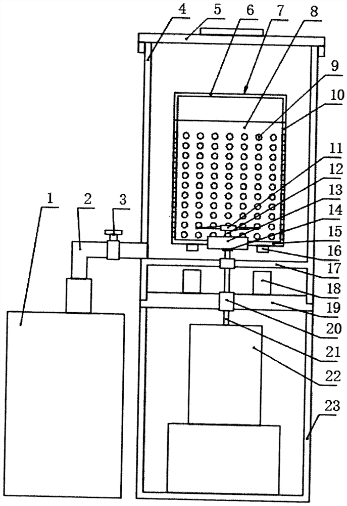
[0147] This example figure 1 As shown, the barrel body 4 is provided with a loam cake 5, the lower end is arranged on the upper end of the shell 23, a liquid outlet pipe 2 is arranged at the bottom of the barrel body, a control valve 3 is arranged on the liquid outlet pipe, and the lower end of the liquid outlet pipe communicates with the container 1.
[0148] The output shaft 21 of the power unit and the cutter shaft 12 are integral long shafts. The cutter shaft is located on the outer edge between the centrifugal cup and the bottom of the bucket body and a fixed structure 14 is arranged on the outer edge. The outer race of the one-way clutch is connected with the bottom 15 of the centrifugal cup through fixed connections such as meshing and clamping, and a cutter 11 is arranged at the upper end of the cutter shaft.
[0149] The upper end opening of the centrifugal cup is provided with an end cover 6, and a plurality of filter holes 10 are provided on the side wall of the cen...
Embodiment 2
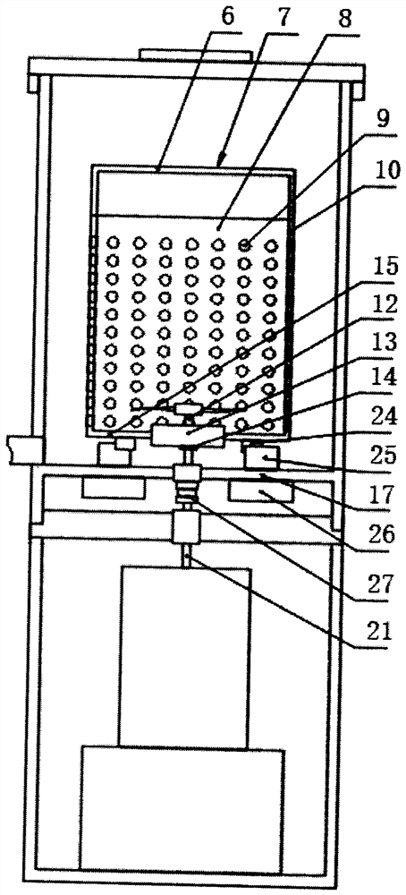
[0160] This example figure 2 As shown, the difference between this embodiment and embodiment 1 is:
[0161] One-way transmission units use one-way bearings.
[0162] The upper end of the output shaft is connected with a half coupling 27, and the lower end of the cutter shaft is connected with a half coupling, and the two half couplings are combined together so that the power unit drives the cutter to rotate through the output shaft, the coupling and the cutter shaft.
[0163] Two baffles 24 are arranged on both sides of the bottom surface of the centrifugal cup, and two limit plates 25 are arranged at the bottom of the barrel body. Driven by the feed mechanism 26, it can extend or retract toward the bottom of the centrifugal cup.
[0164] In this embodiment, the limit of the centrifugal cup is completed by extending the limit plate, that is, when the cutter rotates in the forward direction, due to the friction force of the apple pieces in the centrifugal cup to the centrifu...
Embodiment 3
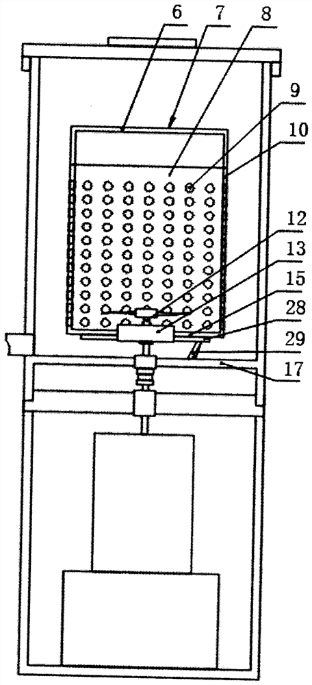
[0168] This example image 3 As shown, the difference between this embodiment and embodiment 2 is:
[0169] One-way drive units use backstops.
[0170] The bottom surface of the centrifugal cup is provided with a ratchet 28 or the shape of the teeth of the ratchet, and one or more pawls 29 are hinged at the bottom of the barrel, and the pawl can block the ratchet or snap into the wheel when the tool rotates forward. The teeth, so that the centrifugal cup stops quickly.
[0171] A ratchet is provided on the bottom surface of the centrifugal cup, and a ratchet or the shape of the teeth of the ratchet is provided at the bottom of the barrel to realize the position limitation of the centrifugal cup. The pawl is arranged on the side wall of the bucket body, and the shape of the teeth on the side wall of the centrifugal cup can also realize the position limitation of the centrifugal cup.
[0172] Others are identical with embodiment 2.
PUM
 Abstract
Description
Claims
Application Information
 - R&D
- Intellectual Property
- Life Sciences
- Materials
- Tech Scout
- Unparalleled Data Quality
- Higher Quality Content
- 60% Fewer Hallucinations
Browse by: Latest US Patents, China's latest patents, Technical Efficacy Thesaurus, Application Domain, Technology Topic, Popular Technical Reports.
© 2025 PatSnap. All rights reserved.Legal|Privacy policy|Modern Slavery Act Transparency Statement|Sitemap|About US| Contact US: help@patsnap.com


