Magnetic field offset particulate matter collecting device and collecting method

A particle collection and magnetic field technology, applied in measuring devices, sampling devices, sampling, etc., can solve the problems of inconvenient use, high maintenance cost, complex structure, etc., and achieve the effect of increasing collection efficiency, fast and efficient collection, and convenient winding.

Pending Publication Date: 2021-06-18
NANJING UNIV OF INFORMATION SCI & TECH
View PDF1 Cites 2 Cited by
  • Summary
  • Abstract
  • Description
  • Claims
  • Application Information

AI Technical Summary

Problems solved by technology

Although the system in this application can effectively enrich particulate matter,

Method used


Image

  • Magnetic field offset particulate matter collecting device and collecting method

Examples


Embodiment 1

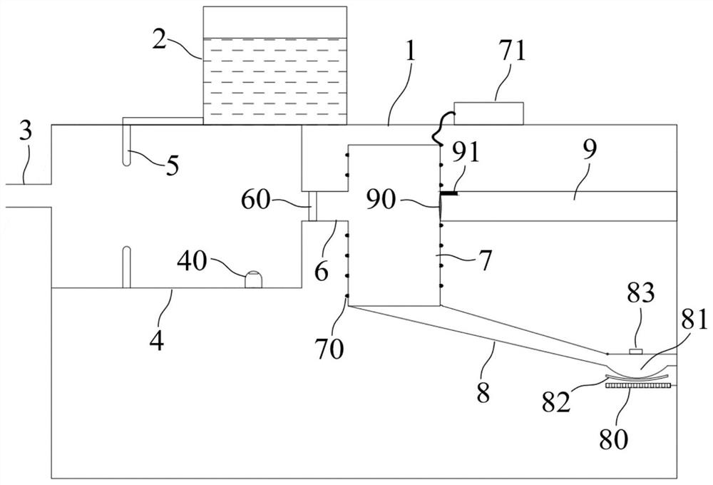
[0053] The magnetic field offset particle collection device of this embodiment includes:

[0054] Rack 1;

[0055] An electrolyte pool 2, which is arranged on the frame 1, and the electrolyte pool 2 contains electrolyte;

[0056] The air inlet 3 is opened at one end of the frame 1;

[0057] An atomization chamber 4, which is arranged in the frame 1, and one end of the atomization chamber 4 communicates with the air inlet 3;

[0058] The atomizing nozzle 5 is fixed on the inner wall of the atomizing chamber 4, and the atomizing nozzle 5 communicates with the electrolyte pool 2 to atomize and spray the electrolyte;

[0059] A gas flow channel 6, one end of which communicates with the other end of the atomization chamber 4, and an exhaust fan 60 is arranged in the gas flow channel 6 to draw air in from the air inlet 3;

[0060] The collection chamber 7 is cylindrical, and its side wall communicates with the other end of the gas flow channel 6, and the side wall of the collection...

Embodiment 2

[0080] This embodiment shows a magnetic field offset particle collection method, using the magnetic field offset particle collection device of Embodiment 1, the specific steps are as follows:

[0081] 1. Liquid preparation, configuring and storing electrolyte in the electrolyte pool 2;

[0082] Two, air extraction, start the exhaust fan 60, and air is drawn into the atomization chamber 4 from the air inlet 3;

[0083] 3. Atomization, start the atomization nozzle 5 to spray the atomized electrolyte into the atomization chamber 4, the aerosol in the air absorbs the atomized electrolyte and is charged, and enters the collection chamber 7 through the gas flow channel 6;

[0084] Four, collect, the surrounding coil 70 is energized, and the vibration generator 91 starts at the same time, periodically vibrates the filter membrane 90, and the aerosol in the collection chamber 7 falls along the collection channel 8;

[0085] 5. Enrichment: the heating unit 80 is heated by electricity ...


PUM


Abstract

The invention discloses a magnetic field offset particulate matter collecting device and method, and belongs to the technical field of collecting equipment. The device comprises a rack; an electrolyte tank; the air inlet formed in one end of the rack; an atomizing chamber of which the one end is communicated with the air inlet; an atomizing nozzle which is fixed on the inner wall of the atomizing chamber, is communicated with the electrolyte tank and is used for atomizing and spraying the electrolyte; a gas flow channel of which one end is communicated with the other end of the atomizing chamber, and is provided with an exhaust fan for sucking air in from the air inlet; a collecting chamber and a collecting channel. The side wall of the collecting chamber is communicated with the other end of the gas flow channel, and an electrified surrounding coil is wound outside the side wall of the collecting chamber; and the collecting channel communicates with the bottom of the collecting chamber, and a heating unit is arranged at the bottom of the collecting channel and used for heating the bottom of the collecting channel. According to the invention, aerosol particles and an atomized electrolyte solution are fully contacted and electrified by using the characteristic that aerosol is easy to adhere and electrified, and falling and collecting of the electrified aerosol particles are accelerated by using magnetic field deviation, so that the aerosol particles are rapidly and efficiently collected.

Description

technical field [0001] The invention belongs to the technical field of collection equipment, and more specifically relates to a magnetic field offset particle collection device and collection method. Background technique [0002] The exhaust gas produced by the catering industry and industry contains a large amount of aerosol particles. Aerosol particles refer to suspended, stranded and settled material particles in the atmosphere, called atmospheric particles, atmospheric particles, or suspended particles. In addition, some people refer to It is called "atmospheric aerosol", and the analysis and research of harmful particles in it is still an important topic at present. [0003] At present, the commonly used enrichment methods for containing aerosol particles include solution absorption method, packed column retention method, filter material retention method and other methods for enrichment treatment, but the effect is not obvious. [0004] After retrieval, Chinese Patent ...

Claims


Application Information

Patent Timeline
IPC IPC(8): B03C1/023G01N1/22
CPCB03C1/023G01N1/2214G01N2001/2223
Inventor 李雨微丁宇刘佳李杰张佳严李佩儒陆天枢杨淋玉赵兴强
Owner NANJING UNIV OF INFORMATION SCI & TECH
Why Eureka
Try Eureka