Eureka AIR delivers breakthrough ideas for toughest innovation challenges, trusted by R&D personnel around the world.

Machining process for improving coaxiality of crankshaft journals

A processing technology, the technology of the crankshaft journal, which is applied in the field of processing technology to improve the coaxiality of the crankshaft journal, can solve the problems of falling, the inability to guarantee the coaxiality of the crankshaft journal, and the large machining error of the crankshaft journal, etc., so that it is not easy to wear , The connection method is simple and stable, and the effect of improving the coaxiality

Inactive Publication Date: 2021-06-18
杭州江滨内燃机配件有限公司
View PDF5 Cites 3 Cited by
  • Summary
  • Abstract
  • Description
  • Claims
  • Application Information

AI Technical Summary

Problems solved by technology

[0003] For some large crankshafts with large dimensions, during the grinding process, only two ends of the crankshaft are stressed, and the middle part of the crankshaft will fall due to gravity, resulting in a large machining error in the grinding of the crankshaft journal, which cannot Guarantee the concentricity of the crankshaft journal

Method used


Image

  • Machining process for improving coaxiality of crankshaft journals
  • Machining process for improving coaxiality of crankshaft journals
  • Machining process for improving coaxiality of crankshaft journals

Examples


Embodiment 1

[0051] S1. Install the crankshaft

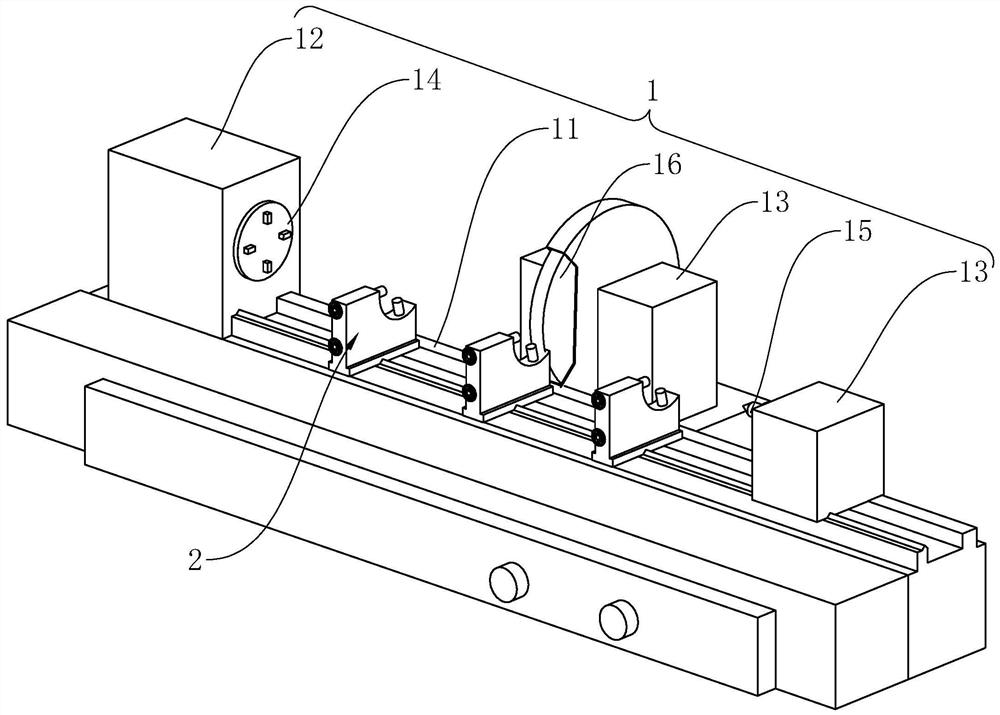
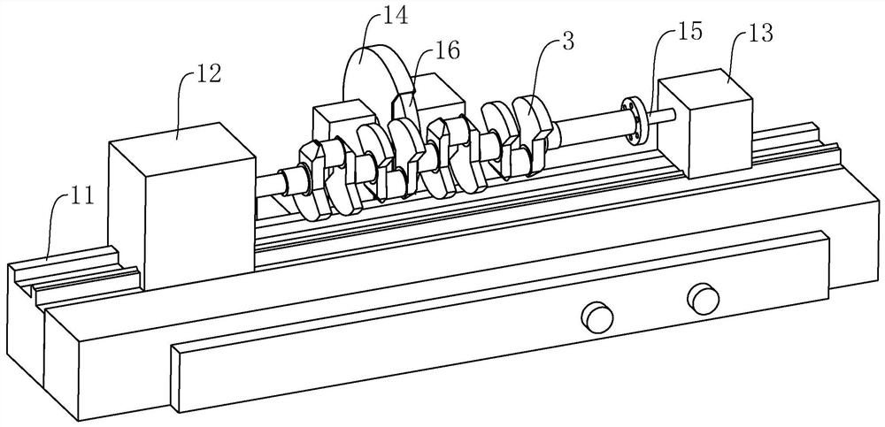
[0052] refer to image 3 , lift the crankshaft 3 and place it on the grinding machine 1, and make the two ends of the crankshaft 3 cooperate with the chuck 15 and the top 16 of the grinding machine 1 respectively, support the crankshaft 3 on the bed 11 of the grinding machine 1, and initially determine the crankshaft 3 The height of the axis relative to the bed 11 of the grinding machine 1 .

[0053] S2. Install center frame 2

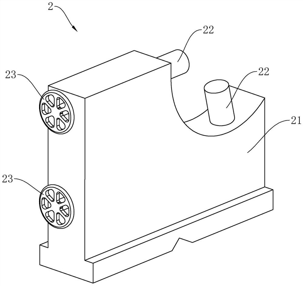
[0054] refer to Figure 4 with Figure 5 , install a plurality of center frames 2 on the bed 11, so that the center frames 2 are evenly arranged along the circumference of the crankshaft 3, and the number of center frames 2 is selected according to the number of journals of the crankshaft 3 to be ground, such as grinding a six-cylinder crankshaft Three center frames 2 are adopted at 3 o'clock, and four center frames 2 are selected for use when grinding the eight-cylinder crankshaft 3. Then turn the two handwheel...

Embodiment 2

[0076] The difference between this embodiment and Embodiment 1 is that step S4 is performed first, and then step S3 is performed.

[0077] If step S3 is performed first and then step S4 is performed, when the universal joint 5 is installed in step S4, it will inevitably contact the crankshaft 3, which will easily cause the position of the crankshaft 3 to move during the installation process, resulting in the axial position of the journal of the crankshaft 3. Changes affect the subsequent grinding process.

[0078] First connect the universal joint 5 between the chuck 15 and the crankshaft 3, and then measure and adjust the position of the crankshaft 3 journal, so as to avoid the impact on the journal position of the crankshaft 3 when installing the universal joint. Make sure that all journal axes of the crankshaft 3 are coincident when grinding.

Embodiment 3

[0080] The difference between Embodiment 3 and Embodiment 1 and Embodiment 2 is that when installing the crankshaft 3 on the grinding machine 1, first install the center frame 2 on the bed 11 of the grinding machine 1, and then directly lift the crankshaft 3 and place it to a plurality of center frames 2, and finally the axial position of the journal of the crankshaft 3 is adjusted and positioned by adjusting the telescopic feet 22 of the center frame 2.

[0081] Although the position of the axis of the journal of the crankshaft 3 can be positioned in the above manner, after the crankshaft 3 is placed on the center frame 2, the relative position of the axis of the journal of the crankshaft 3 and the axis of the chuck 15 of the grinding machine 1 cannot be guaranteed, which is easy The large deviation between the journal axis of the crankshaft 3 and the axis of the chuck 15 of the grinding machine 1 will cause the deformation of the universal joint 5 to be too large, resulting i...


PUM


Abstract

The invention relates to a machining process for improving the coaxiality of crankshaft journals, and belongs to the technical field of crankshaft machining. The process comprises the machining steps that a crankshaft is placed above a machine body of a grinding machine; a plurality of central frames are installed on the machine body of the grinding machine, and each central frame supports one journal at the corresponding position of the crankshaft on the grinding machine; the position of the axis of each journal of the crankshaft relative to the machine body of the grinding machine is measured, and the positions of the axes of all the journals of the crankshaft are consistent by adjusting telescopic feet of the central frames; a universal joint is installed at the shaft end of the crankshaft, and the universal joint and a chuck of the grinding machine are connected together; and the grinding machine is started to operate to grind each journal of the crankshaft to be of designed size. In the process of grinding the crankshaft journals, the crankshaft is supported on the grinding machine only under the action of the central frames, so that the middle portion of the crankshaft is not prone to drooping as a result of gravity, the axis position error of the crankshaft journals and the grinding machine chuck is counteracted under the action of the axis change of the universal joint, and the coaxiality of the crankshaft journals after grinding is improved.

Description

technical field [0001] The present application relates to the field of crankshaft machining, in particular to a machining process for improving the coaxiality of crankshaft journals. Background technique [0002] The crankshaft is one of the important components in the internal combustion engine. The coaxiality of each journal of the crankshaft determines the smoothness and stability of the internal combustion engine during operation. At present, when grinding crankshaft journals, two thimbles of the grinding machine are used to support the crankshaft on the bed of the grinding machine, and then the journals of the crankshaft are ground with emery wheels. [0003] For some large crankshafts with large dimensions, during the grinding process, only two ends of the crankshaft are stressed, and the middle part of the crankshaft will fall due to gravity, resulting in a large machining error in the grinding of the crankshaft journal, which cannot Ensure the coaxiality of the cran...

Claims


Application Information

Patent Timeline
IPC IPC(8): B24B1/00B24B5/42B24B49/00B24B41/06
CPCB24B1/00B24B5/42B24B5/421B24B49/00B24B41/062
Inventor 田超杰
Owner 杭州江滨内燃机配件有限公司
Why Eureka
Eureka Blog
Learn More