
Wafer edge grinding method and device

A kind of grinding processing and edge technology, which is applied in the direction of grinding drive device, metal processing equipment, grinding/polishing equipment, etc., can solve the problem of decreased stability of wafer edge grinding accuracy, affecting the quality of wafer grinding surface, and inability to Complete edge shape and other issues to achieve the effect of reducing edge chipping and chipping, reducing the probability of edge chipping and chipping, and stabilizing position adjustment

Active Publication Date: 2021-06-18
HUAZHONG UNIV OF SCI & TECH
View PDF11 Cites 2 Cited by
  • Summary
  • Abstract
  • Description
  • Claims
  • Application Information

AI Technical Summary

Problems solved by technology

Due to the use of surface grinding, the grinding spindle is installed in the Z-axis direction perpendicular to the wafer. The self-weight of the grinding spindle will affect the motion accuracy of the Z-axis, resulting in a decrease in the stability of the wafer edge grinding accuracy.
At the same time, due to the use of surface grinding, large grinding force and grinding heat will be generated during the grinding process, which will affect the quality of the wafer grinding surface and aggravate the chipping phenomenon during the wafer grinding process
Different edge shapes have a great influence on the quality of edge grinding and the reliability of subsequent processing technology. However, the inclination angle of the grinding wheel of general wafer edge grinding equipment is fixed, and it is impossible to complete edge shapes at different angles, resulting in Machine processing adaptability is weak

Method used


Image

  • Wafer edge grinding method and device
  • Wafer edge grinding method and device
  • Wafer edge grinding method and device

Examples


Embodiment Construction

[0049] The present invention will be further described below in conjunction with specific embodiments.

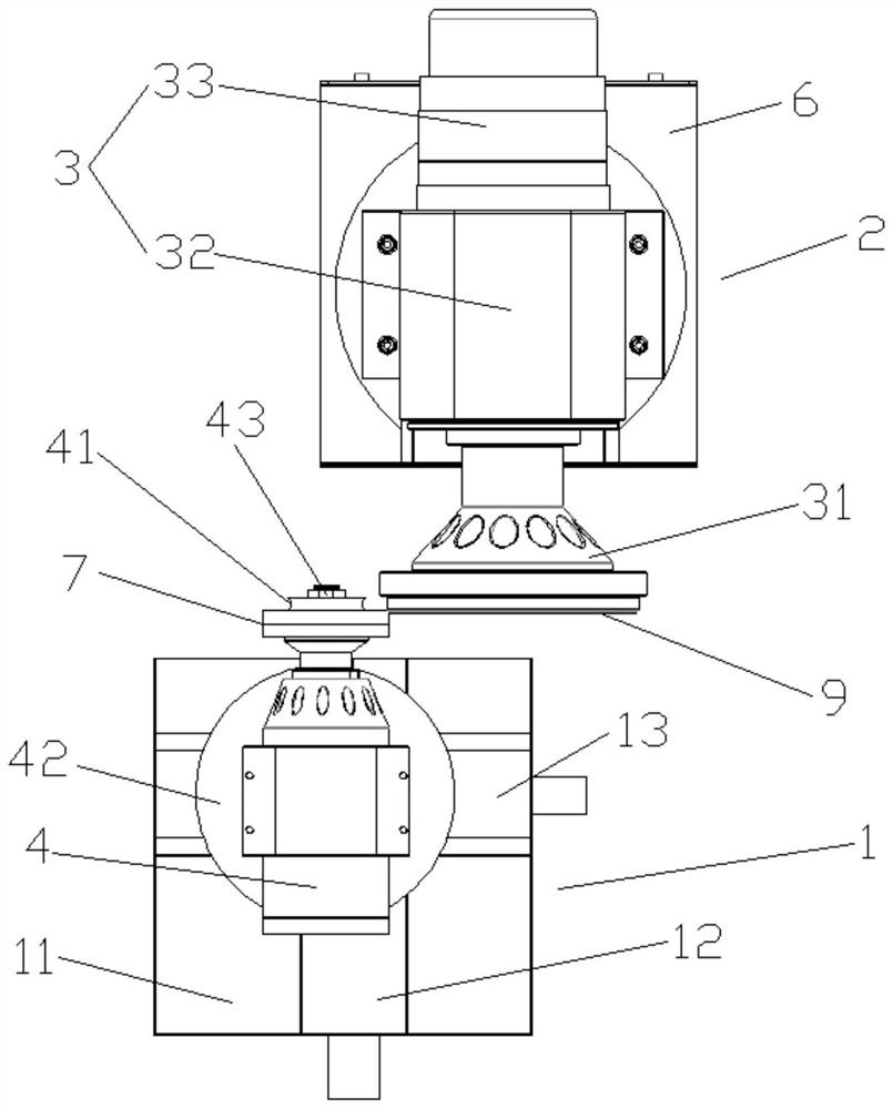
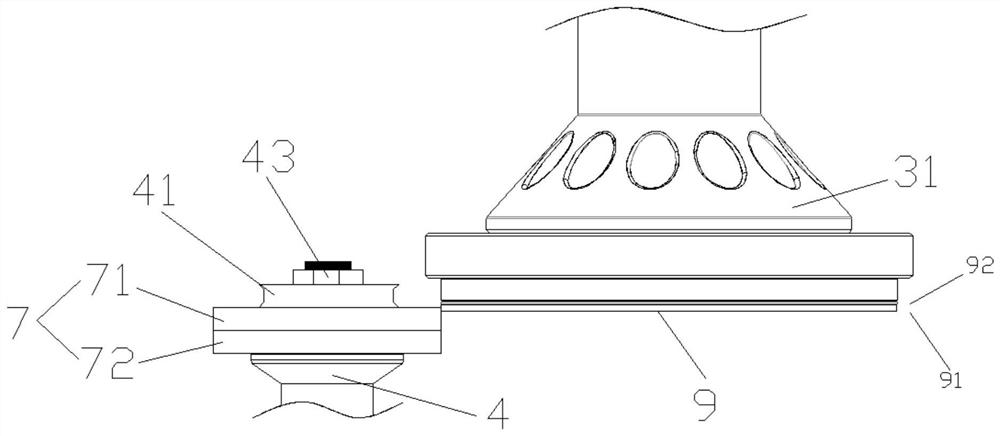
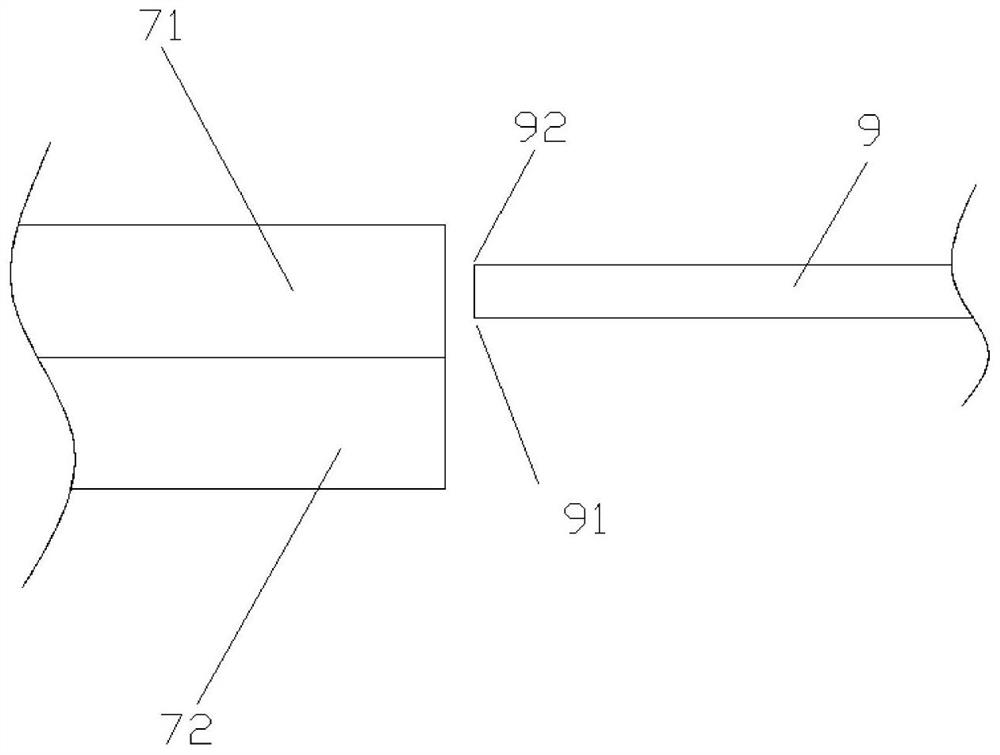
[0050] Such as figure 1 , figure 2 and image 3 As shown, a wafer edge grinding device includes an edge grinding mechanism 1 and a fixing mechanism 2, the fixing mechanism 2 is used to fix the wafer 9, and the edge grinding mechanism 1 is used to grind the edge of the wafer 9;

[0051]The edging mechanism 1 includes a first base plate 11 and a grinder 4 located on the first base plate 11. The first base plate 11 is provided with a two-axis slide table, and the two-axis slide table adopts the existing X-axis and Y-axis two-axis slide table. The two-axis slide table includes a first slide table 12 and a second slide table 13 arranged sequentially from bottom to top. The first slide table 12 can drive the second slide table 13 to move back and forth through motor control, and the second slide table 13 passes through The motor control can drive the grinding machine 4 to mov...


PUM


Abstract

The invention discloses a wafer edge grinding machining method and device, and belongs to the technical field of wafer machining. The device comprises an edge grinding mechanism and a fixing mechanism, the edge grinding mechanism comprises a first bottom plate and a grinding machine located on the first bottom plate, a first grinding wheel is arranged at the end, close to the fixing mechanism, of the grinding machine, the fixing mechanism comprises a second bottom plate and an adsorption device located on the second bottom plate, the adsorption device comprises a hollow motor and a vacuum adsorption pump, the end, close to the edge grinding mechanism, of the hollow motor is connected with a suction cup head used for adsorbing wafers, the suction cup head is connected with the vacuum adsorption pump through a pipeline, and the first grinding wheel comprises a first grinding ring and a second grinding ring. Grinding force and grinding heat in the wafer grinding process can be effectively reduced, the positions of the grinding machine and the wafer are convenient and stable to adjust, the angle can be finely adjusted when the wafers rotate, the edge grinding quality of the wafers is improved, steps of different shapes can be formed at the edges of the wafers, and the probability of edge breakage and fragmentation when the wafers are ground and thinned is reduced.

Description

technical field [0001] The invention belongs to the technical field of wafer processing, and more specifically relates to a wafer edge grinding method and device. Background technique [0002] The existing wafer edge grinding process is generally plane grinding with the grinding wheel perpendicular to the wafer. The grinding wheel is clamped on the grinding spindle, and the Z linear axis perpendicular to the wafer and the Y linear axis parallel to the wafer drive the air spindle to achieve grinding. Each linear axis is composed of a screw and a motor, and the depth and width of edge grinding are controlled by the Z axis and the Y axis respectively. Due to the use of surface grinding, the grinding spindle is installed in the Z-axis direction perpendicular to the wafer, and the self-weight of the grinding spindle will affect the motion accuracy of the Z-axis, resulting in a decrease in the stability of the wafer edge grinding accuracy. At the same time, due to the use of surf...

Claims


Application Information

Patent Timeline
Patent Type & Authority Applications(China)
IPC IPC(8): B24B9/06B24B27/00B24B47/12B24B47/22
CPCB24B9/065B24B27/0076B24B27/0084B24B47/22B24B47/12
Inventor 许剑锋侍大为张建国郑正鼎于世超
Owner HUAZHONG UNIV OF SCI & TECH
Learn More