Clamping force controllable air pressure equipment

A controllable, air-pressure technology, applied in chucks, manipulators, manufacturing tools, etc., can solve problems such as gripper freezing and carton falling off

Inactive Publication Date: 2021-06-18
潘新凤
View PDF0 Cites 1 Cited by
  • Summary
  • Abstract
  • Description
  • Claims
  • Application Information

AI Technical Summary

Problems solved by technology

[0003] Due to the low temperature inside the popsicle factory, and the popsicles will be packed inside the carton after production, the inner side of the gripper of the controllable air pressure manipulator clamps the popsicle carton, and the inner concave lines will adhere to it. Moisture, when the gripper is in contact with the cold popsicle carton for a long time, it is easy to make the moisture inside the gripper gradually freeze, so that the carton with a large number of popsicles will fall off due to gravity

Method used


Image

  • Clamping force controllable air pressure equipment
  • Clamping force controllable air pressure equipment
  • Clamping force controllable air pressure equipment

Examples


Embodiment 1

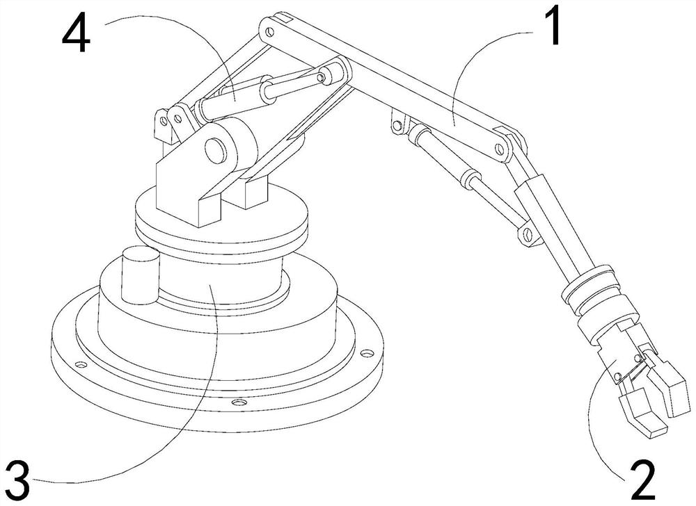
[0026] For example figure 1 -example Figure 5 Shown:

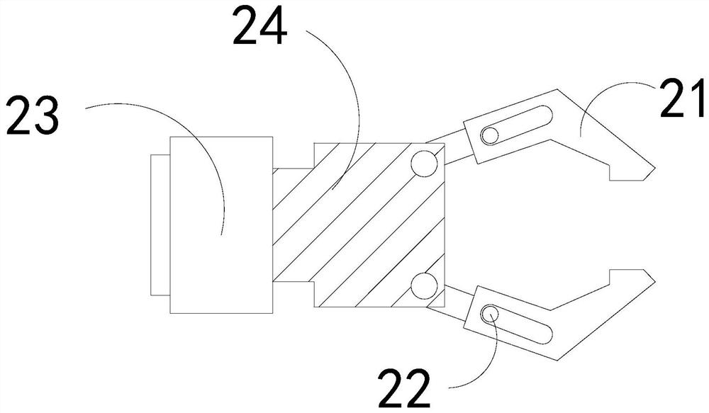
[0027] The present invention provides a pneumatic device with controllable clamping force. Its structure includes a linkage rod 1, a clamper 2, a base 3, and a pneumatic rod 4. 4 is connected to the side of the linkage rod 1, and the holder 2 is installed at the front end of the linkage rod 1; the holder 2 includes a clamping plate 21, a vibrating ball 22, an engaging plate 23, and a connecting plate 24, The clamping plate 21 is movably engaged with the right end of the coupling plate 24 , the vibrating ball 22 is mounted inside the clamping plate 21 , and the coupling plate 24 is embedded in the right side of the connecting plate 23 .

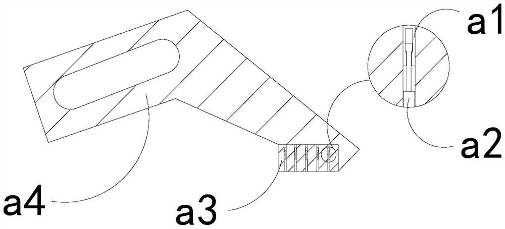
[0028] Wherein, the clamping plate 21 includes a built-in frame a1, a telescopic rod a2, a contact plate a3, and a plate body a4. The built-in frame a1 is embedded in the inner position of the contact plate a3. Movable engagement, the contact plate a3 and the plate body a4 are an integ...

Embodiment 2

[0034] For example Figure 6 -example Figure 8 Shown:

[0035] Wherein, the ice-breaking mechanism b3 includes an outer ring c1, an overhanging block c2, a middle solid block c3, and a connecting rod c4. Installed at the inner center of the outer ring c1, the connecting rod c4 is embedded in the outer surface of the middle solid block c3, and there are four outstretched blocks c2, which are evenly distributed in a circular shape on the outer ring c1 , through the throwing force generated by the rotation of the mechanism, the overhanging block c2 can be extended outward along the outer ring c1, so that the overhanging block c2 can push away the ice surface on the surface of the outer ring c1.

[0036] Wherein, the overhanging block c2 includes a crushing groove c21, a receiving plate c22, an impact block c23, and a bottom plate c24. In combination, the impact block c23 is embedded and fixed on the upper surface of the bottom plate c24, and the crushing groove c21 is in the ...


PUM


Abstract

The invention discloses clamping force controllable air pressure equipment. The equipment structurally comprises a linkage rod, a clamping device, a base and an air pressure rod, wherein the linkage rod is movably clamped with the upper end of the base, the air pressure rod is connected with the side of the linkage rod, the clamping device is installed at the front end of the linkage rod, due to the gravity of a telescopic rod, the telescopic rod can extend outwards along a contact plate when extrusion of an ice sucker paper box is lost, so that the telescopic rod can push an ice layer attached to the surface of the contact plate to be broken, then melted ice water obtained after the ice layers are scraped can be guided out downwards through a lower discharging cavity, the situation that water is attached to the inner sides of the clamping plates, and the clamping plates are frozen when encountering cold is effectively avoided, through thrust generated by water entering the lower discharging cavity on an ice breaking mechanism, an outward extending block can extend outwards along a connecting rod, so that the outward extending block can push an ice layer on the outer surface of an external ring to be broken, and then water melted by the ice layer inside the lower discharging cavity can be absorbed through a water absorbing block.

Description

technical field [0001] The invention relates to the field of pneumatic systems and equipment, in particular to a controllable clamp force pneumatic equipment. Background technique [0002] The clamping force controllable pneumatic manipulator is mainly used for clamping and transporting the items. The clamper on the front end of the clamping force controllable pneumatic manipulator clamps the items, and then the pneumatic pump drives the clamper to hold the object. Clamping, and finally, the controllable clamping force pneumatic manipulator drives the items to be transported across regions. Based on the above description, the inventors found that the existing clamping force controllable pneumatic device mainly has the following deficiencies, for example: [0003] Due to the low temperature inside the popsicle factory, and the popsicles will be packed inside the carton after production, the inner side of the gripper of the controllable air pressure manipulator clamps the pops...

Claims


Application Information

Patent Timeline
Patent Type & Authority Applications(China)
IPC IPC(8): B25J15/00B65G47/90
CPCB25J15/00B65G47/90
Inventor 张清芬
Owner 潘新凤
Why Eureka
Try Eureka