Bearing quenching equipment

A technology of quenching equipment and bearings, applied in the direction of quenching equipment, heat treatment equipment, furnaces, etc., can solve the problems of drain pipe blockage temperature, troublesome operation, unevenness, etc., and achieve the effect of easy heat dissipation, easy cleaning, simple and efficient operation

Pending Publication Date: 2021-06-18
常州高度新能源科技有限公司
View PDF0 Cites 7 Cited by
  • Summary
  • Abstract
  • Description
  • Claims
  • Application Information

AI Technical Summary

Problems solved by technology

[0007] The purpose of the present invention is to provide a kind of bearing quenching equipment to solve the troublesome operation proposed in the above-mentioned background technology. The deposited iron filings may cause the blockage of the drain pipe and the uneven temperature inside the quenching tank will easily affect the quality of the bearing.

Method used


Image

  • Bearing quenching equipment
  • Bearing quenching equipment
  • Bearing quenching equipment

Examples


Embodiment Construction

[0023] The technical solutions in the embodiments of the present invention will be clearly and completely described below with reference to the accompanying drawings in the embodiments of the present invention. Obviously, the described embodiments are only a part of the embodiments of the present invention, but not all of the embodiments. Based on the embodiments of the present invention, all other embodiments obtained by those of ordinary skill in the art without creative efforts shall fall within the protection scope of the present invention.

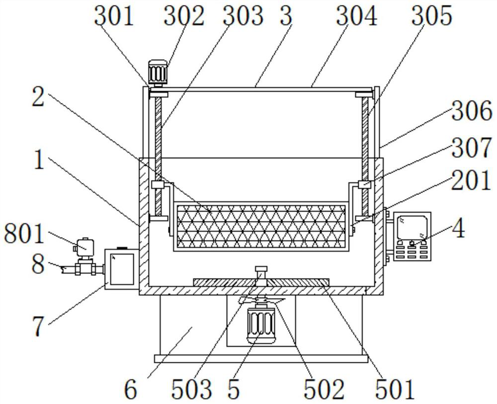
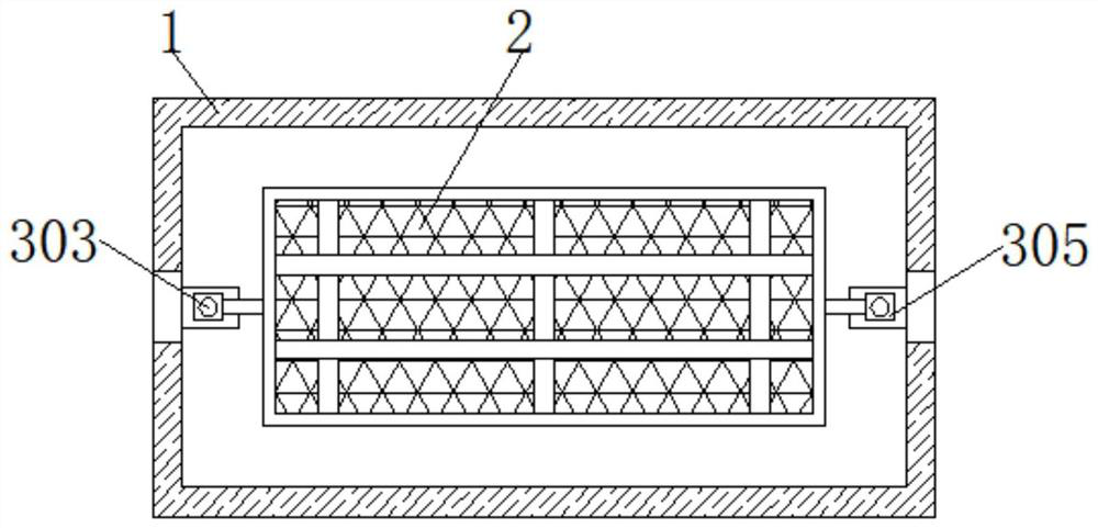
[0024] see Figure 1-4 , an embodiment provided by the present invention: a bearing quenching equipment, including a quenching tank 1, a controller 4 and a base 6, the model of the controller 4 can be FHR-211, and the interior of the quenching tank 1 is movably set through the transmission mechanism 3 There is a placing basket 2, and the transmission mechanism 3 includes a first roller 301, a first motor 302, a first screw rod 303, a ...


PUM


Abstract

The invention relates to the technical field of bearing heat treatment devices, in particular to bearing quenching equipment. The defects that in the prior art, operation is troublesome, a liquid discharging pipe is prone to being blocked, and the temperature of all positions in a quenching tank is uneven are overcome. The bearing quenching equipment comprises the quenching tank, a controller and a base, and a containing basket is movably arranged in the quenching tank through a transmission mechanism. The transmission mechanism comprises a first roller, a first motor, a first lead screw, a belt, a second lead screw, supporting vertical plates and sliding blocks, the first lead screw and the second lead screw are installed on the two sides of the quenching tank correspondingly, the first roller is connected to the top end of the first lead screw and the top end of the second lead screw in a sleeving mode correspondingly, and the sliding blocks are connected to the first lead screw and the second lead screw in a sleeving mode correspondingly. Discharging is convenient, and the work efficiency is high. A filtering cavity is formed in the bottom end of one side of the quenching tank, a second motor is arranged in the middle of the bottom end of the quenching tank, and a rotating shaft, a scraping plate and fan blades are arranged at the output end of the second motor, so that scrap iron is prevented from being deposited in the quenching tank.

Description

technical field [0001] The invention relates to the technical field of bearing heat treatment, in particular to a bearing quenching equipment. Background technique [0002] Bearing is an important mechanical part, which can reduce the friction coefficient during the movement of the mechanical rotating body. After the bearing is produced, it needs to be quenched to improve its strength, hardness, wear resistance, fatigue strength and toughness. It is to first heat the bearing to a temperature above the critical temperature, keep it for a certain period of time, and then cool it at a rate greater than the critical cooling rate to ensure that the austenite can be cooled at a rate exceeding the critical cooling rate, thereby obtaining the martensite structure and obtaining the purpose of quenching. The cooling capacity requirements of the liquid are very different for different steel grades; [0003] The existing bearing quenching equipment generally has the following problems:...

Claims


Application Information

Patent Timeline
Patent Type & Authority Applications(China)
IPC IPC(8): C21D9/40C21D1/63
CPCC21D1/63C21D9/40
Inventor 黄振
Owner 常州高度新能源科技有限公司
Why Eureka
Try Eureka