Rotor blade precision forging structure and preparation method thereof

A precision forging technology for rotor blades, applied in the direction of blade support components, mechanical equipment, engine components, etc., can solve the deformation of the inlet and exhaust edges of the blade tip section, cannot effectively guarantee the processing quality, and the inlet and exhaust edges are easy to tear and deform and other problems, to achieve the effect of ensuring contour, simple structure and increasing thickness

Active Publication Date: 2021-06-18
AECC AVIATION POWER CO LTD
View PDF7 Cites 2 Cited by
  • Summary
  • Abstract
  • Description
  • Claims
  • Application Information

AI Technical Summary

Problems solved by technology

Several sections near the tip of the blade have poor rigidity due to lack of tenon fixation and reinforcement. During the forging process, they are most affected by factors such as elastic-plastic deformation of the metal material and residual stress release during heat treatment. The profile, torsion angle and bending are all Easy to deform and out of tolerance
In addition, the thinner part of the precision forged blade body is generally in the area near the intake and exhaust edges of the tip section, while the along-path extension section of the blade tip is thinner than the blade tip section thickness. The edge is easy to tear and deform, which will cause the deformation of the inlet and exhaust edges of the blade tip section. At present, it mainly relies on manual inspection during processing, which cannot effectively guarantee the processing quality and reduces the processing efficiency.

Method used


Image

  • Rotor blade precision forging structure and preparation method thereof
  • Rotor blade precision forging structure and preparation method thereof

Examples


preparation example Construction

[0029] A method for preparing a precision forging structure of a rotor blade, comprising the following steps,

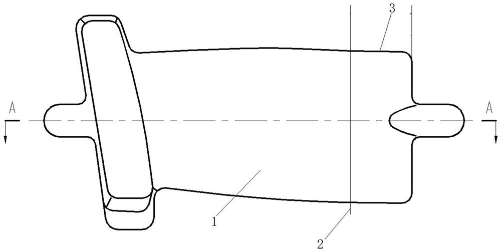
[0030] S1, according to the structure of the rotor blade precision forging, create a tool plane within the range of the homeopathic extension of the rotor blade precision forging body;

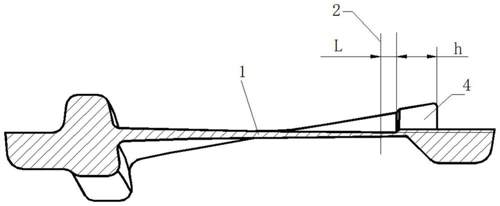
[0031] The dimension h of the reinforcing rib 4 along the length direction of the precision forging body 1 of the rotor blade is 5 mm to 10 mm, and the distance L between one end surface of the reinforcing rib 4 and the plane where the blade tip section 2 is located is not less than 5 mm; Chord length of forging body 1;

[0032] S2, take the created tool plane as the boundary, and use the cross section of the stiffener as the offset surface to perform surface offset to form a stiffener structure model;

[0033] Specifically, use the "split body" function to split the fine forging of the rotor blade into two parts, the rest and the unthickened ribs, to realize the split model of the ...

Embodiment 1

[0036] For precision forgings of rotor blades, the tip of the blade extends along the trend of 10 mm, and the method of the present invention is used to design reinforcing ribs on the back side of the extension of the tip of the blade along the trend. The method of designing ribs is operated by UG three-dimensional modeling software, and the implementation steps are as follows:

[0037] 1) Determine the size of the rib: the length of the rib is 5mm, one end of the rib is aligned with the outermost end of the airfoil, and the other end is kept at a distance of 5mm from the blade tip section; the width dimension includes the entire chord length range; the thickness dimension is selected according to actual needs. mm;

[0038] 2) Create a tool plane: according to the length dimension determined in step 1), create a tool plane within the scope of the extension section;

[0039] 3) Split the three-dimensional shape of the precision forging blade: take the tool plane created in ste...

Embodiment 2

[0043] For precision forgings of rotor blades, the blade tip extends 15 mm along the trend, and the method of the present invention is used to design reinforcing ribs on the back side of the blade tip along the direction of extension. The method of designing ribs is operated by UG three-dimensional modeling software, and the implementation steps are as follows:

[0044]1) Determine the size of the rib: the length is 10mm, one end is aligned with the outermost end of the airfoil, and the other end is kept 5mm away from the blade tip section; the width includes the entire chord length range; the thickness is 5mm according to actual needs;

[0045] 2) Create a tool plane: according to the length dimension determined in step 1), create a tool plane within the scope of the extension section;

[0046] 3) Split the three-dimensional shape of the precision forging blade: take the tool plane created in step 2) as the boundary, use the "split body" function to split the three-dimensiona...


PUM


Abstract

The invention discloses a rotor blade precision forging structure and a preparation method. A reinforcing rib is arranged on the back surface of a homeopathic extending section, the reinforcing rib is used as a support of the homeopathic extending section, and the strength of the homeopathic extending section close to an air inlet and exhaust edge area is improved by utilizing the reinforcing rib, so that the strength of a blade tip homeopathic extending section in the polishing process is ensured; the end surface of one end of the reinforcing rib and the plane where the blade tip section is located are arranged at intervals, so that the influence of the reinforcing rib on the blade tip structure is prevented; meanwhile, the size of the reinforcing rib in the length direction of a rotor blade precision forging body is smaller than the length of the homeopathic extending section, so that the reinforcing rib is prevented from interfering with the air inlet and exhaust edge of the blade tip section, the influence degree of factors such as elastic-plastic deformation of a metal material and residual stress release in the heat treatment process on a blade tip portion is reduced, and the profile tolerance, the torsion angle and the bending of the blade tip section are guaranteed; and the reinforcing rib is designed, so that the air inlet and exhaust edge of the blade tip section is protected in the polishing process, deformation is eliminated, the machining precision is improved, and the machining efficiency is also improved.

Description

technical field [0001] The invention belongs to the field of precision forging blade processing, and relates to a rotor blade precision forging structure and a preparation method thereof. Background technique [0002] In order to meet the processing requirements of precision forging blades, generally, rotor blade precision forgings are designed with a homeopathic extension section with a length of 10 mm to 15 mm above the effective section of the blade tip. Several sections near the tip of the blade have poor rigidity due to lack of tenon fixation and reinforcement. During the forging process, they are most affected by factors such as elastic-plastic deformation of the metal material and residual stress release during heat treatment. The profile, torsion angle and bending are all Easy to deform and out of tolerance. In addition, the thinner part of the precision forged blade body is generally in the area near the intake and exhaust edges of the tip section, while the along-...

Claims


Application Information

Patent Timeline
Patent Type & Authority Applications(China)
IPC IPC(8): F01D5/14B21K3/04
CPCF01D5/147F01D5/141B21K3/04Y02E10/72
Inventor 王江辉弥国华王毅辉王昊陈哲曹四化汪晶董要增
Owner AECC AVIATION POWER CO LTD
Why Eureka
Try Eureka