Smoke exhaust system and side-draft range hood

A technology of smoke exhaust system and smoke exhaust port, which is applied in the field of kitchen utensils, can solve the problems of large occupied space, large volume of smoke collection hood, unsatisfactory oil fume suction effect, etc., and achieve the goal of increasing flow efficiency and enhancing suction effect Effect

Pending Publication Date: 2021-06-18
CHINABEST HOME APPLIANCE
View PDF0 Cites 0 Cited by
  • Summary
  • Abstract
  • Description
  • Claims
  • Application Information

AI Technical Summary

Problems solved by technology

The traditional side-suction range hood has a relatively large volume, that is, it occupies a large space, and is not suitable for small-sized kitchens. There are some light and thin side-suction range hoods on the market. The volume of the fume hood is small, but the air inlet of the wind cabinet of these light and thin side suction range hoods is limited by the air outlet of the fume collecting hood and is located at the bottom of the wind cabinet, making the smoke exhaust path more complicated. , the flow efficiency of the oil fume is low, which leads to the unsatisfactory effect of the above-mentioned light and thin side suction range hood on the oil fume in the cooking environment

Method used


Image

  • Smoke exhaust system and side-draft range hood
  • Smoke exhaust system and side-draft range hood
  • Smoke exhaust system and side-draft range hood

Examples


Embodiment Construction

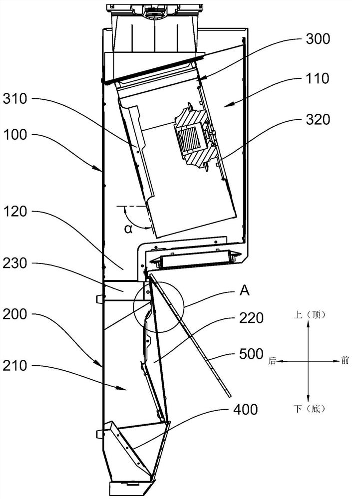
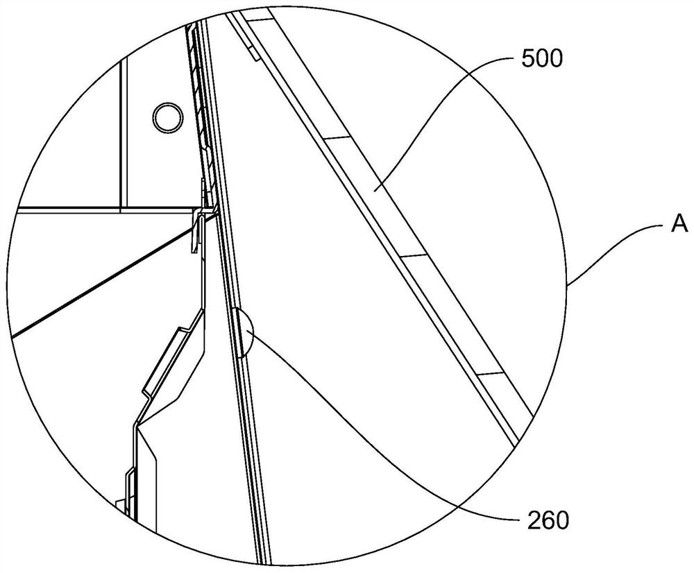
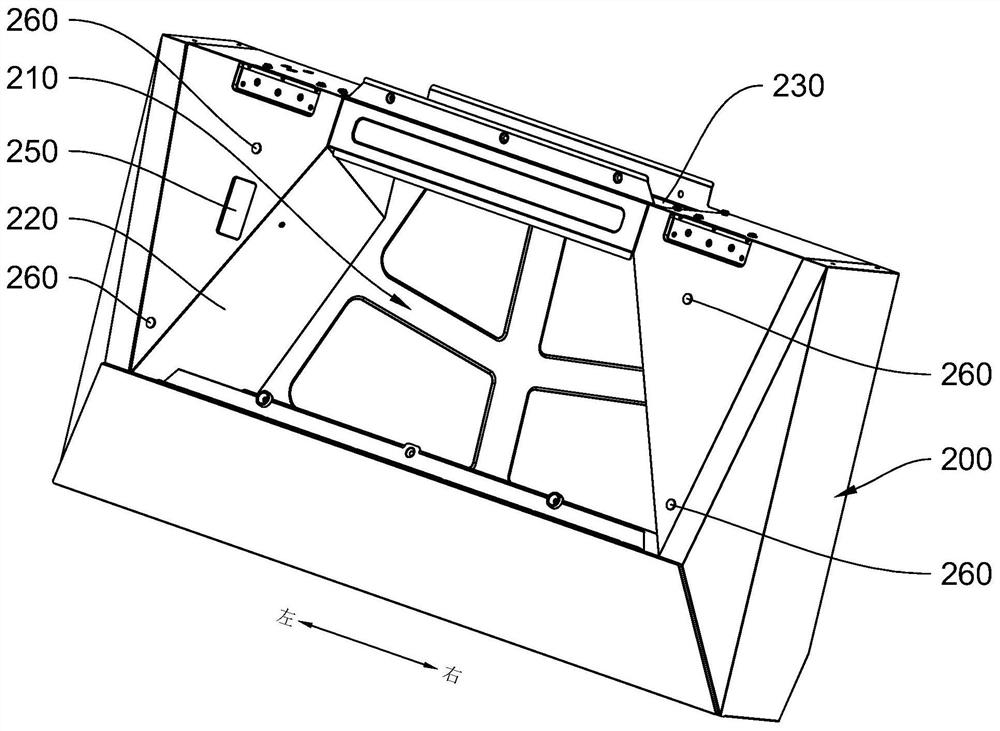
[0025] Embodiments of the present invention are described in detail below, examples of which are shown in the drawings, wherein the same or similar reference numerals designate the same or similar elements or elements having the same or similar functions throughout. The embodiments described below by referring to the figures are exemplary only for explaining the present invention and should not be construed as limiting the present invention.

[0026] In the description of the present invention, it should be understood that if it involves orientation descriptions, for example, the orientation or positional relationship indicated by up, down, front, back, left, right, etc. is based on the orientation or positional relationship shown in the drawings, only It is for the convenience of describing the present invention and simplifying the description, but does not indicate or imply that the referred device or element must have a specific orientation, be constructed and operated in a ...


PUM


Abstract

The invention discloses a smoke exhaust system and a side-draft range hood. The side-draft range hood comprises the smoke exhaust system. The smoke exhaust system comprises an air cabinet, a smoke collecting hood and a fan, wherein a first containing cavity is formed in the air cabinet, a first smoke exhaust port is formed in the top of the air cabinet, and a first smoke inlet is formed in the rear side of the bottom of the air cabinet; the smoke collecting hood is arranged at the bottom of the air cabinet, a smoke collecting cavity is formed in the smoke collecting hood, a second smoke inlet is formed in the front side of the smoke collecting hood, and a second smoke exhaust port connected with the first smoke inlet is formed in the top of the smoke collecting hood; and the fan is arranged in the first containing cavity, a first air inlet and an air outlet are formed in a shell of the fan, the first air inlet is located in the rear side of the shell of the fan, the air outlet is connected with the first smoke exhaust port, and the included angle alpha between the plane where the first air inlet is located and the horizontal plane is an obtuse angle. By the adoption of the structure, the number of times of reversing before cooking fume enters the first air inlet is reduced, the flowing efficiency before the cooking fume enters the first air inlet can be improved, and thus the effect of sucking away the cooking fume in the cooking environment is improved.

Description

technical field [0001] The invention relates to the field of kitchen utensils, in particular to a smoke exhaust system and a side suction range hood. Background technique [0002] In the prior art, the side-suction range hood usually includes a fan cabinet and a smoke collection hood arranged at the bottom of the fan cabinet. A smoke collection cavity connected to the fan cabinet is arranged inside the smoke collection The smoke inlet of the smoke chamber is equipped with an oil net. The oil fume generated during cooking enters the smoke collection chamber from the smoke inlet under the action of the fan inside the air cabinet, and then enters the air cabinet from the smoke collection chamber, and then passes through The smoke exhaust pipe connected to the wind cabinet is exhausted. The traditional side-suction range hood has a relatively large volume, that is, it occupies a large space, and is not suitable for small-sized kitchens. There are some light and thin side-suctio...

Claims


Application Information

Patent Timeline
IPC IPC(8): F24C15/20
CPCF24C15/2071
Inventor 莫康赞刘伟龙廖毅宇孔维通乌胜斌
Owner CHINABEST HOME APPLIANCE
Why Eureka
Try Eureka