
Converter station heat recovery air conditioning system and control method thereof, and converter station

An air-conditioning system and heat recovery technology, which is applied in the field of air-conditioning, can solve the problems of smaller heat exchanger space, reduced heat exchange area of ​​heat exchanger, and reduced heat exchange efficiency of heat exchanger, so as to improve heat exchange efficiency and discharge The effect of clear cloth and reducing space occupation

Active Publication Date: 2021-06-18
SHANDONG LONGERTEK TECH CO LTD
View PDF5 Cites 0 Cited by
  • Summary
  • Abstract
  • Description
  • Claims
  • Application Information

AI Technical Summary

Problems solved by technology

[0003] According to the current humanized design of the power station, it is necessary to increase the worker's lounge and the owner's coffee break room. To ensure that the two rooms are warm in winter and cool in summer, the heat exchanger needs to have two pipelines, and one pipeline is used for fluid circulation to achieve cooling. , and the other pipeline is used for fluid circulation to realize heating. Since there are two pipelines in the heat exchanger, the space inside the heat exchanger occupied by each pipeline is relatively small, so that the heat exchanger can be used in cooling or cooling. The heat exchange area decreases during heating, resulting in a decrease in the heat exchange efficiency of the heat exchanger

Method used


Image

  • Converter station heat recovery air conditioning system and control method thereof, and converter station
  • Converter station heat recovery air conditioning system and control method thereof, and converter station

Examples


Embodiment

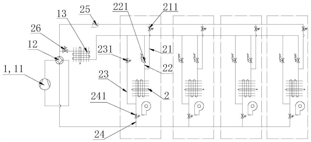
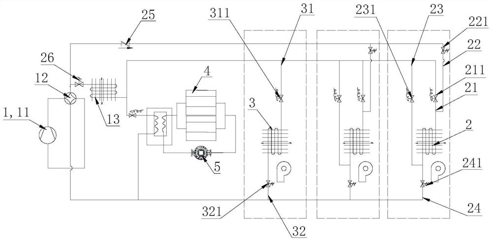
[0034] Such as figure 1 and figure 2 As shown, the present invention provides a heat recovery air-conditioning system for a power exchange station, which includes a heat exchange cycle main circuit 1, and the heat exchange cycle main circuit 1 includes a compressor 11, a four-way valve 12 and a condenser 13, and also includes several heat exchangers, There is a pipeline in the heat exchanger, and the two ends of at least one pipeline are respectively connected to at least two branches connected to different positions of the main heat exchange cycle 1, and each branch and the main heat exchange cycle 1 are equipped with The control components that control the on-off of the pipeline, and the heat exchanger is connected to the heat exchange cycle main circuit 1 in the form of a switchable condenser 13 or an evaporator through each control component.

[0035] In the embodiment of the present invention, by adjusting the control components on each branch and the control component ...


PUM


Abstract

The invention relates to a converter station heat recovery air conditioning system and a control method thereof, and a converter station. The converter station heat recovery air conditioning system comprises a heat exchange circulation main path, the heat exchange circulation main path comprises a compressor, a four-way valve and a condenser, the system further comprises a plurality of heat exchangers, a pipeline is arranged in each heat exchanger, the two ends of at least one pipeline are connected with at least two branches connected to different positions of the heat exchange circulation main path respectively, each branch and the heat exchange circulation main path are each provided with a control assembly for controlling connection and disconnection of the pipeline, and the heat exchangers are connected to the heat exchange circulation main path through the control assemblies in a switchable condenser or evaporator mode. By adjusting the control assemblies on the branches and the control assembly on the heat exchange circulation main path, fluid during refrigeration and fluid during heating of the heat exchangers both pass through the same pipeline, so that the heat exchange area of the heat exchangers during refrigeration or heating is increased, and the heat exchange efficiency of the heat exchangers can be improved. The invention further provides a control method of the converter station heat recovery air conditioning system and the converter station heat recovery air conditioning system.

Description

technical field [0001] The invention belongs to the technical field of air conditioning, and in particular relates to a heat recovery air conditioning system for a substation, a control method thereof, and a substation. Background technique [0002] At present, with the rapid growth of the number of new energy vehicles in my country, the charging and discharging time of vehicle batteries is long, which can no longer meet the application needs of car owners. As an emerging industry, the battery swap station has begun to develop. When the battery power of new energy vehicles is insufficient, the user can quickly replace the battery at a nearby swap station, allowing the replaced battery to be charged and discharged at the swap station, saving the user's charging and discharging time. When charging and discharging the battery, the battery will heat up. If the temperature is higher than the normal use temperature of the battery, the life of the battery will be greatly shortened....

Claims


Application Information

Patent Timeline
Patent Type & Authority Applications(China)
IPC IPC(8): F24F1/0063F24F11/84F24F12/00F24F13/30
CPCF24F12/00F24F1/0063F24F13/30F24F11/84Y02B30/56
Inventor 朱洪磊张永利
Owner SHANDONG LONGERTEK TECH CO LTD
Learn More