Supercharge Your Innovation With Domain-Expert AI Agents!

System and method for measuring relative deformation of soil layer rolled by road roller in real time

A relatively deformable, road roller technology, applied in radio wave measurement systems, measurement devices, satellite radio beacon positioning systems, etc., can solve problems such as poor accuracy, difficulty in achieving effective measurement, and inability to meet control accuracy.

Active Publication Date: 2021-06-18
TSINGHUA UNIV
View PDF5 Cites 0 Cited by
  • Summary
  • Abstract
  • Description
  • Claims
  • Application Information

AI Technical Summary

Problems solved by technology

This method is used in the measurement of rolling deformation of unmanned road rollers. It is greatly affected by temperature and the accuracy is poor, so it is difficult to achieve effective measurement.
[0004] The rolling deformation sensor has high requirements on the stability of the device and the anti-vibration performance during the machine walking process. If the sonar sensor is used to measure the rolling deformation of the roller, large errors will occur
The working scene of the road roller has its particularity. Generally, there will be various factors such as uneven road surface and operation vibration, which will cause large errors in the sonar sensor, which cannot meet the requirements of control accuracy.

Method used


Image

  • System and method for measuring relative deformation of soil layer rolled by road roller in real time
  • System and method for measuring relative deformation of soil layer rolled by road roller in real time

Examples


Embodiment Construction

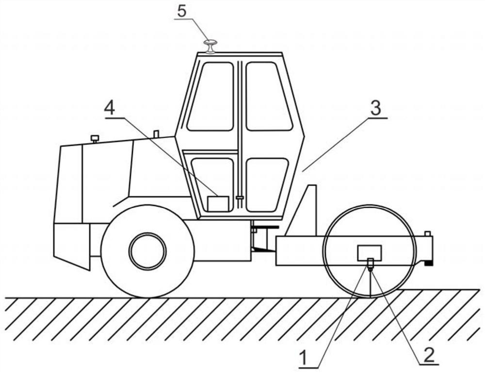
[0022] System and method for real - time measurement of roller rolling soil layer

[0023] It is characterized in that the mounting frame 1, the laser scanning device 2, the GPS / BDS satellite positioning device 5, an on-board signal analyzer 4; mounting bracket is provided in the center of the roller 3 front wheel left and right axle, mounting laser scan on the mounting bracket. Device, the laser scanning device maintains a vertical attitude of the soil surface in the front-rear direction in the front-rear direction; the laser ray of the laser scanning device is scanned by the roller travel direction; the GPS / BDS satellite positioning device is set on the junction machine, at the roller Set an onboard signal analyzer in the driving platform;

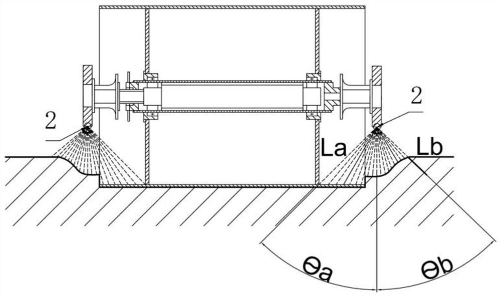
[0024] The laser ray of the laser scanning device converts the real-time relative distance LA of the surface of the top surface of the collected front wheel, conversion to the difference between the real-time relative distance Lb of the ...


PUM


Abstract

The invention discloses a system and a method for measuring relative deformation of a soil layer rolled by a road roller in real time. The system is characterized by comprising a mounting frame, a laser scanning device, a satellite positioning device and an on-board signal analyzer. An installation support is arranged in the center of a left axle and a right axle of a front wheel of the road roller, a laser scanning device is installed on the installation support, and laser rays of the laser scanning device are kept in a posture perpendicular to a soil layer surface; a satellite positioning device is arranged on the top of the road roller, and an on-board signal analyzer is arranged in a driving platform of the road roller; a laser scanning device has the characteristics of high ray speed, high photoelectric conversion speed, small concentration degree and dispersion degree, high measurement distance precision and multiple light beams such as rays and reflected rays during working, and is used for measuring the difference value of the relative distance between a road surface which is rolled on the inner side of a front wheel of the road roller and a road surface which is not rolled on the outer side of the front wheel, so that the deformation of the road roller during rolling is judged, the measurement of the rolling precision is realized, the error caused by the vibration state of the road roller is reduced and the rolling deformation isefficiently measuredin real time.

Description

Technical field [0001] The present invention belongs to the technical field of construction machinery, and it is specifically that system and method for real - time measuring the relative deformation of the roller roller layer. Background technique [0002] With the rapid development of unmanned driving technology, the unmanned roller began in the actual use of infrastructure, energy, water conservancy and other projects. The measurement accuracy of the roller rolling deformation amount not only affects its travel operation, but also affects the quality of the rolling operation, but also related to security issues. The amount of rolling deformation of the roller is to ensure the key to its normal construction work, so the technique of the road lane laser scanning device is essential in the unmanned roadway. [0003] In the field of rolling deformation measurement technology, there are currently several measurement platforms based on RSS, and there is a sound-sensor and laser sens...

Claims


Application Information

Patent Timeline
IPC IPC(8): G01B11/16G01B11/00G01S19/14G01S19/33
CPCG01B11/16G01B11/002G01S19/14G01S19/33
Inventor 刘天云孙玉军张建民王玉孝王恩志芦永政
Owner TSINGHUA UNIV
Features
  • R&D
  • Intellectual Property
  • Life Sciences
  • Materials
  • Tech Scout
  • Unparalleled Data Quality
  • Higher Quality Content
  • 60% Fewer Hallucinations
Learn More