
Die casting burr measuring system and method

A measurement system and technology of die castings, applied in the field of die castings, can solve problems such as the inability to actually measure the length of burrs or flashes, and the inability to accurately measure the precision of production machining

Active Publication Date: 2021-06-18
江苏中科云控智能工业装备有限公司
View PDF8 Cites 3 Cited by
  • Summary
  • Abstract
  • Description
  • Claims
  • Application Information

AI Technical Summary

Problems solved by technology

[0003] After the production of die castings is completed, a certain amount of burrs or flashes often appear on the outer surface, but the length of the burrs or flashes cannot be actually measured, so the machining accuracy of the production machinery cannot be accurately measured, so we propose a Die casting burr measurement system and method for solving the problems raised above

Method used


Image

  • Die casting burr measuring system and method
  • Die casting burr measuring system and method
  • Die casting burr measuring system and method

Examples


Embodiment 1

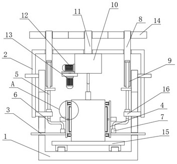
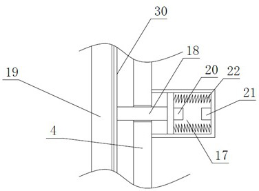
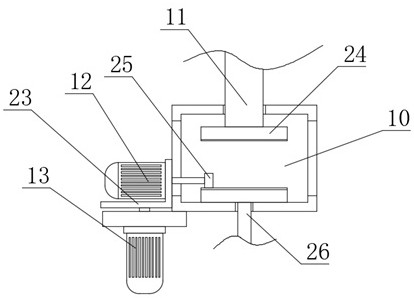
[0040] refer to Figure 1-9 , a die casting burr measurement system is proposed in this embodiment, including a mounting frame 1, a processor is fixedly installed on the mounting frame 1, a mobile frame 2 is slidably connected to the mounting frame 1, and the top inner wall of the mobile frame 2 is fixedly installed There is an installation box 10, a slide assembly is installed on the installation box 10, and a drive motor 12 is installed on the slide assembly, and the drive motor 12 is electrically connected to the processor, and the inner walls on both sides of the installation frame 1 are rotatably connected with screw rods 5, And the thread directions on the two screw rods 5 are opposite, and the two screw rods 5 are all threadedly connected with the mobile frame 2, and the bottom inner wall of the mounting frame 1 is slidably connected with a slide plate 15, and the output shaft of the driving motor 12 is connected with the two screw rods 5 and the slide plate respectively...

Embodiment 2

[0045] refer to Figure 9 , the present invention also proposes a detection method of a die-casting burr measurement system, including the die-casting burr measurement system, and further comprising the following steps:

[0046] S1: by placing the die casting to be tested on the slide 15;

[0047] S2: Start the drive motor 12, and under the engagement transmission of the drive gear 25 and the gear plate 24 on the driving shaft 11, the two rotating columns 8 can be rotated, so that the mobile frame 2 can be moved downward, and When the two screw rods 5 rotate, the two Z-shaped rods 6 can be driven to rotate to the side close to each other. At this time, the two connecting covers 7 can push the two mounting plates 4 close to each other until the four contact sensors are all When in contact with the die casting, the contact sensor will send a work instruction to the processor to make the drive motor 12 suspend work. The calculation formula of the contact sensor is:

[0048] ...


PUM


Abstract

The invention discloses a die casting burr measuring system and method, and aims to solve the problem that the machining precision of production machinery cannot be accurately measured due to the fact that a certain amount of burrs or flashes often appear on the outer surface of the existing die casting after the production of the die casting is completed, but the lengths of the burrs or the flashes cannot be actually measured. The burr measuring system comprises a mounting frame, a processor is fixedly mounted on the mounting frame, a moving frame is slidably connected to the mounting frame, a mounting box is fixedly mounted on the inner wall of the top of the moving frame, a sliding assembly is mounted on the mounting box, a driving motor is mounted on the sliding assembly, and the driving motor is electrically connected with the processor. According to the invention, the flash generated on the die casting can be accurately measured and simulated and displayed, so that the precision of a production machine can be accurately controlled, the precision of the production machine can be accurately adjusted, and the use convenience is good.

Description

technical field [0001] The invention relates to the technical field of die castings, in particular to a measurement system and method for burrs of die castings. Background technique [0002] Die-casting is a kind of pressure-casting part. It uses a pressure-casting mechanical die-casting machine equipped with a casting mold to pour liquid copper, zinc, aluminum or aluminum alloy into the feed port of the die-casting machine, and passes through the die-casting machine. Die casting, casting copper, zinc, aluminum parts or aluminum alloy parts of the shape and size limited by the mold, such parts are usually called die castings. Die-casting parts have different names in different places, such as die-casting parts, pressure castings, die-casting parts, die-casting aluminum, die-casting zinc parts, die-casting copper parts, copper die-casting parts, zinc die-casting parts, aluminum die-casting parts aluminum die-casting parts, aluminum die-casting parts Alloy castings, aluminum ...

Claims


Application Information

Patent Timeline
Patent Type & Authority Applications(China)
IPC IPC(8): G01B21/02G01N33/00
CPCG01B21/02G01N33/00
Inventor 章明蒋亮胡世警赵伟程周嘉龙
Owner 江苏中科云控智能工业装备有限公司
Learn More